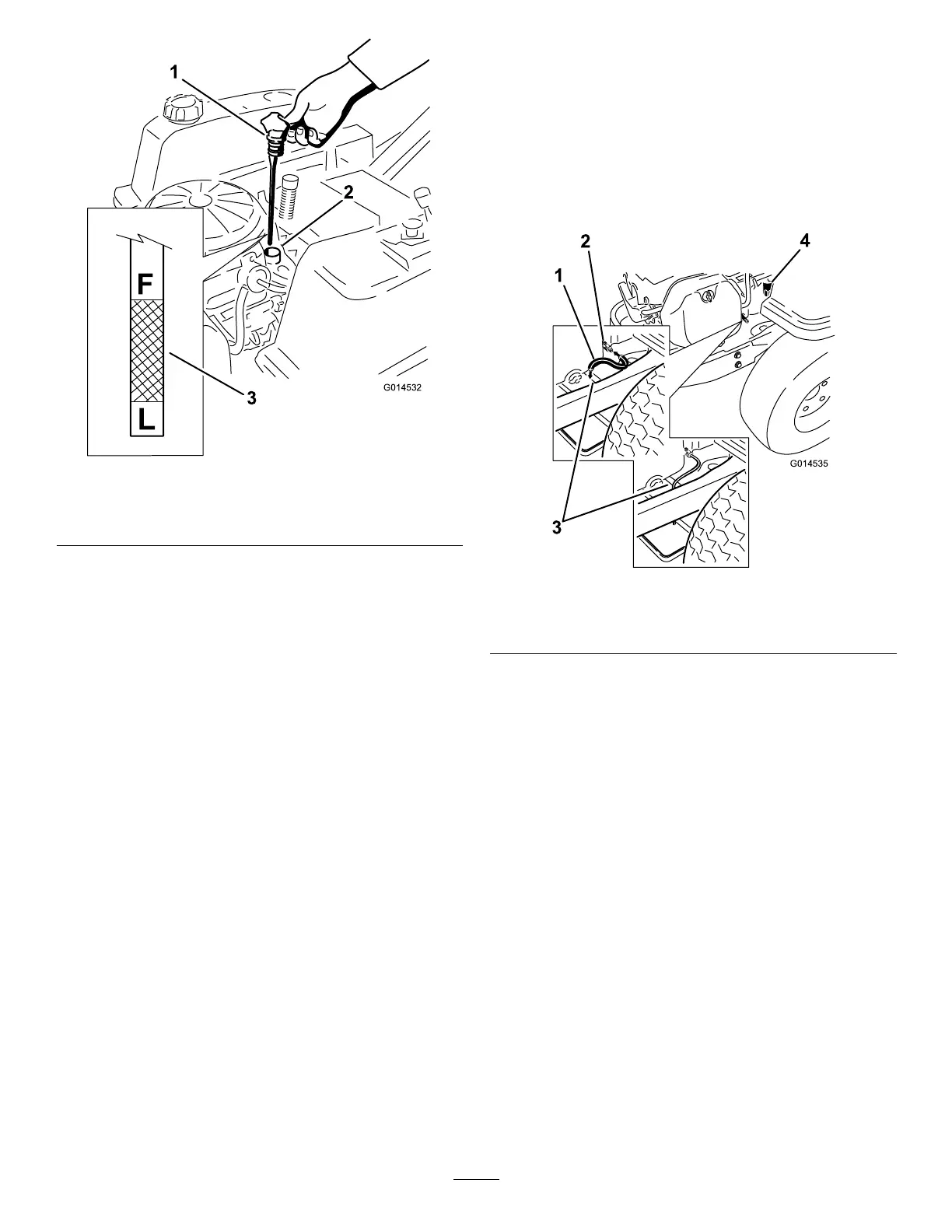
Figure30
1.Oildipstick3.Oillevel
2.Fillertube
5.Removethedipstickandchecktheoillevel.
(Figure30).
Theoillevelshouldbeupto,butnotover,theF
markonthedipstick.
6.Ifthelevelislow ,addoilofthepropertype,upto
theFmarkonthedipstick.Alwayscheckthelevel
withthedipstickbeforeaddingmoreoil.
Note:Topreventextensiveenginewearordamage,
alwaysmaintaintheproperoillevelinthecrankcase.
Neveroperatetheenginewiththeoillevelbelowthe
“L”markoroverthe“F”markonthedipstick.
ChangingtheOilandtheFilter
ServiceInterval:Every100hours—Changetheengine
oilandlter.
RellwithserviceclassSG,SH,SJorhigheroilas
speciedinthe“ViscosityGrades”table.
Changetheoilandlterwhiletheengineisstillwarm.
Theoilwillowmorefreelyandcarryawaymore
impurities.Makesuretheengineislevelwhenlling,
checking,orchangingtheoil.
Changetheoilandoillterasfollows:
1.Parkthemachinesothatthedrainsideisslightly
lowerthantheoppositesidetoassuretheoildrains
completely.
2.Disengagethebladecontrolswitchandmovethe
motioncontrolsoutwardtotheparkposition.
3.Stoptheengine,removethekey,andwaitforall
movingpartstostopbeforeleavingtheoperating
position.
4.Cleantheareaaroundthedrainvalveandonthe
machineframe.Locatetheoildrainhoseandslide
itoverthedrainvalve(
Figure31).
Figure31
1.Oildrainhose3.Endofframe
2.Drainvalve
4.Oillter
5.Placetheoppositeendoftheoildrainhoseoverthe
endoftheframe(Figure31).
6.Placeapanunderneathmachinedirectlybelowthe
drainhoseasshowninFigure32.
27