8.Loosentherearlockingnutonthehangerbracket
justenoughtomovethebracket(Figure52).
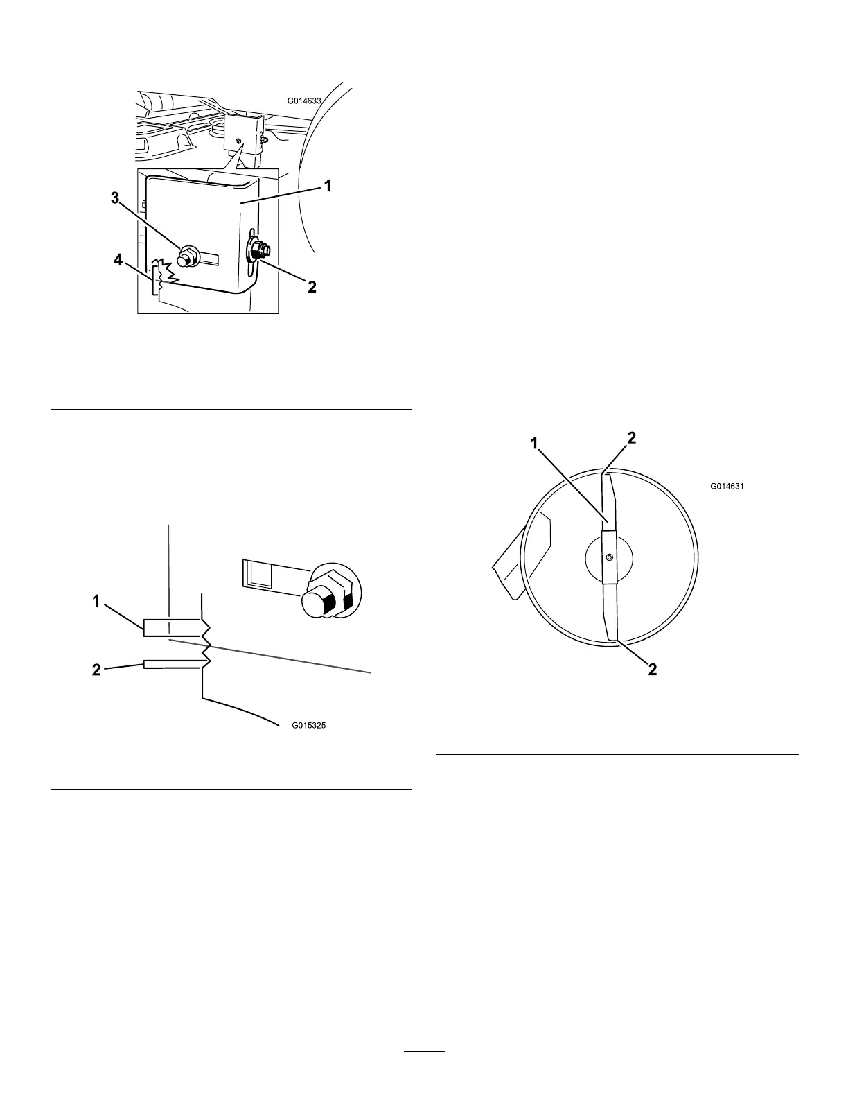
Figure52
1.Hangerbracket
3.Sidelockingnut,slotted
position.
2.Rearlockingnut4.Adjustmentnotches
9.Usethenotchesontheweldedbrackettomeasure
theamountofadjustment.Eachnotchsurfaceis
equivalentto0.25inch,whileasinglesideis0.125
inch(Figure53).Adjusttheheightofthemower
decktothedesiredheight.
Figure53
1.0.25inch2.0.125inch
10.Stopthedeckattheadjustedpositionandtightenthe
rearlockingnutonthehangerbrackettoholdthe
newposition(Figure52).Tightenthesidelocking
nutonthehangerbracket.
11.Continuelevelingthedeckbycheckingthe
front-to-rearbladeslope;refertoAdjustingthe
Front-to-RearBladeSlope.
AdjustingtheFront-to-RearBlade
Slope
Checkthefront-to-rearbladelevelanytimeyouinstall
themower.Ifthefrontofthemowerismorethan
5/16inch(7.9mm)lowerthantherearofthemower,
adjustthebladelevelusingthefollowinginstructions:
1.Parkthemachineonalevelsurfaceanddisengage
thebladecontrolswitch.
2.Movethemotioncontrolleversoutwardtothe
parkposition,stoptheengine,removethekey,and
waitforallmovingpartstostopbeforeleavingthe
operatingposition.
3.Settheheight-of-cutlevertomiddleposition.
Note:Checkandadjusttheside-to-sideblade
levelifyouhavenotcheckedthesetting;referto
Side-to-SideLeveling.
4.Carefullyrotatethebladessotheyarefacingfront
torear(
Figure54).
Figure54
1.Bladefronttorear
2.Measurefromthetipofthebladetotheatsurfacehere
5.Measurefromthetipofthefrontbladetotheat
surfaceandthetipoftherearbladetotheat
surface(
Figure54).Ifthefrontbladetipisnot
1/16-5/16inch(1.6-7.9mm)lowerthantherear
bladetip,adjustthefrontlocknut.
6.Toadjustthefront-to-rearbladeslope,rotatethe
adjustmentnutinthefrontofthemower(
Figure55).
37