6.Measurefromthetipofthefrontbladetotheat
surfaceandthetipoftherearbladetotheat
surface(Figure45).Ifthefrontbladetipisnot
1/16-5/16inch(1.6-7.9mm)lowerthantherear
bladetip,adjustthefrontlocknut.
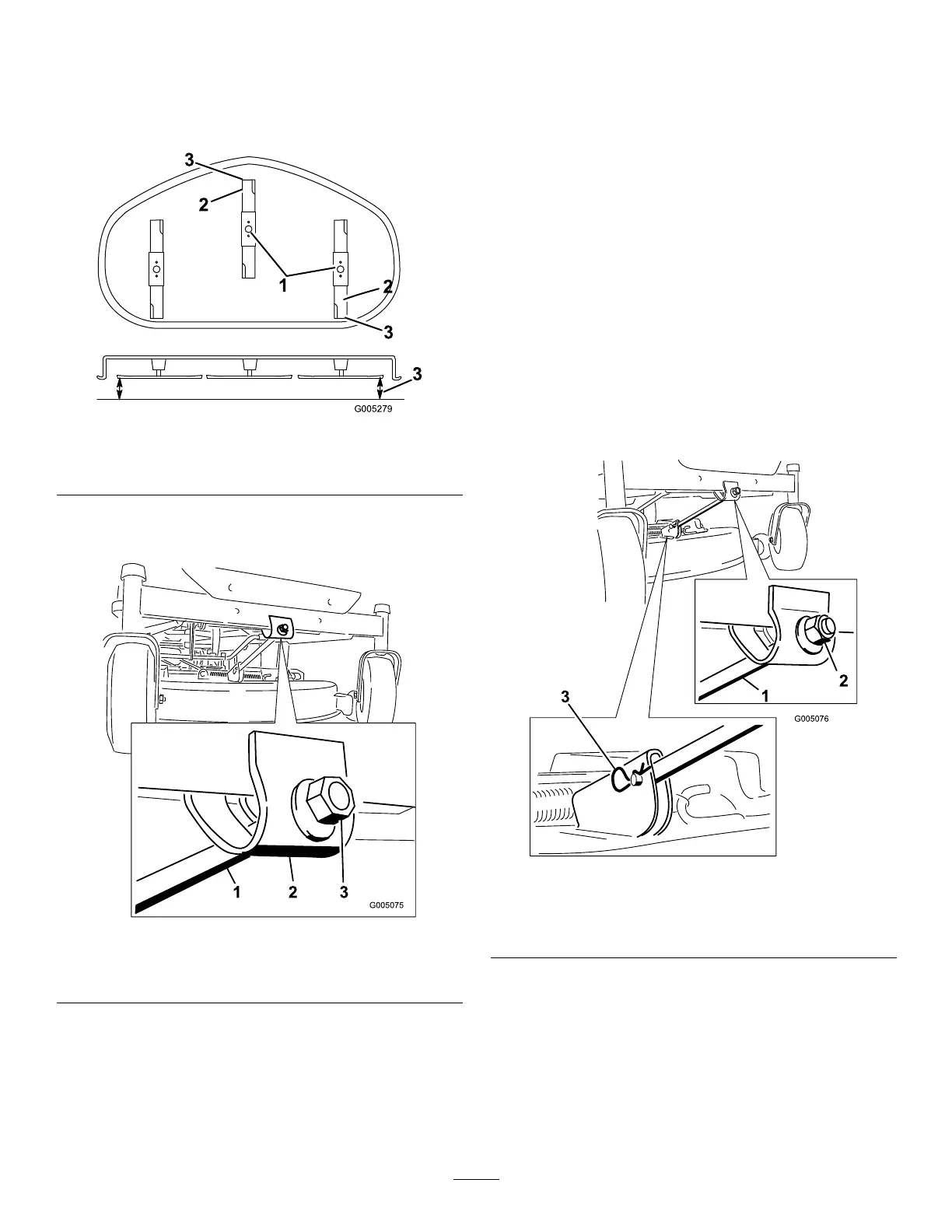
Figure45
1.Bladesfronttorear
3.Measurehere
2.Outsidecuttingedges
7.Toadjustthefront-to-rearbladeslope,rotatethe
adjustmentnutinthefrontofthemower(Figure46).
Figure46
1.Adjustingrod3.Locknut
2.Adjustingblock
8.Toraisethefrontofthemower,tightenthe
adjustmentnut.Tolowerthefrontofthemower,
loosentheadjustmentnut.
9.Afteradjustment,checkthefront-to-rearslopeagain.
Continueadjustingthenutuntilthefrontbladetip
is1/16-5/16inch(1.6-7.9mm)lowerthantherear
bladetip(Figure45).
10.Whenthefront-to-rearbladeslopeiscorrectcheck
theside-to-sidelevelofthemoweragain;referto
LevelingtheMowerfromSide-to-Side.
RemovingtheMower
1.Parkthemachineonalevelsurfaceanddisengage
thebladecontrolswitch.
2.Movethemotioncontrolleversoutwardtothe
parkposition,stoptheengine,removethekey,and
waitforallmovingpartstostopbeforeleavingthe
operatingposition.
3.Lowertheheight-of-cutlevertothelowestposition.
4.Removethehairpincotterandclevispinfromthe
frontsupportrod(Figure47).Carefullylowerthe
frontofthemowerdecktotheground.
Figure47
1.Frontsupportrod3.Hairpincotterandclevis
pin
2.Lockingnut
5.Liftthemowerdeckandhangerbracketsclearof
therearliftrodandlowerthemowercarefullyto
theground(Figure48).
35