Maintenance
54
2
M-4197
14
3
7
5
6
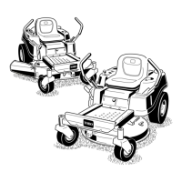
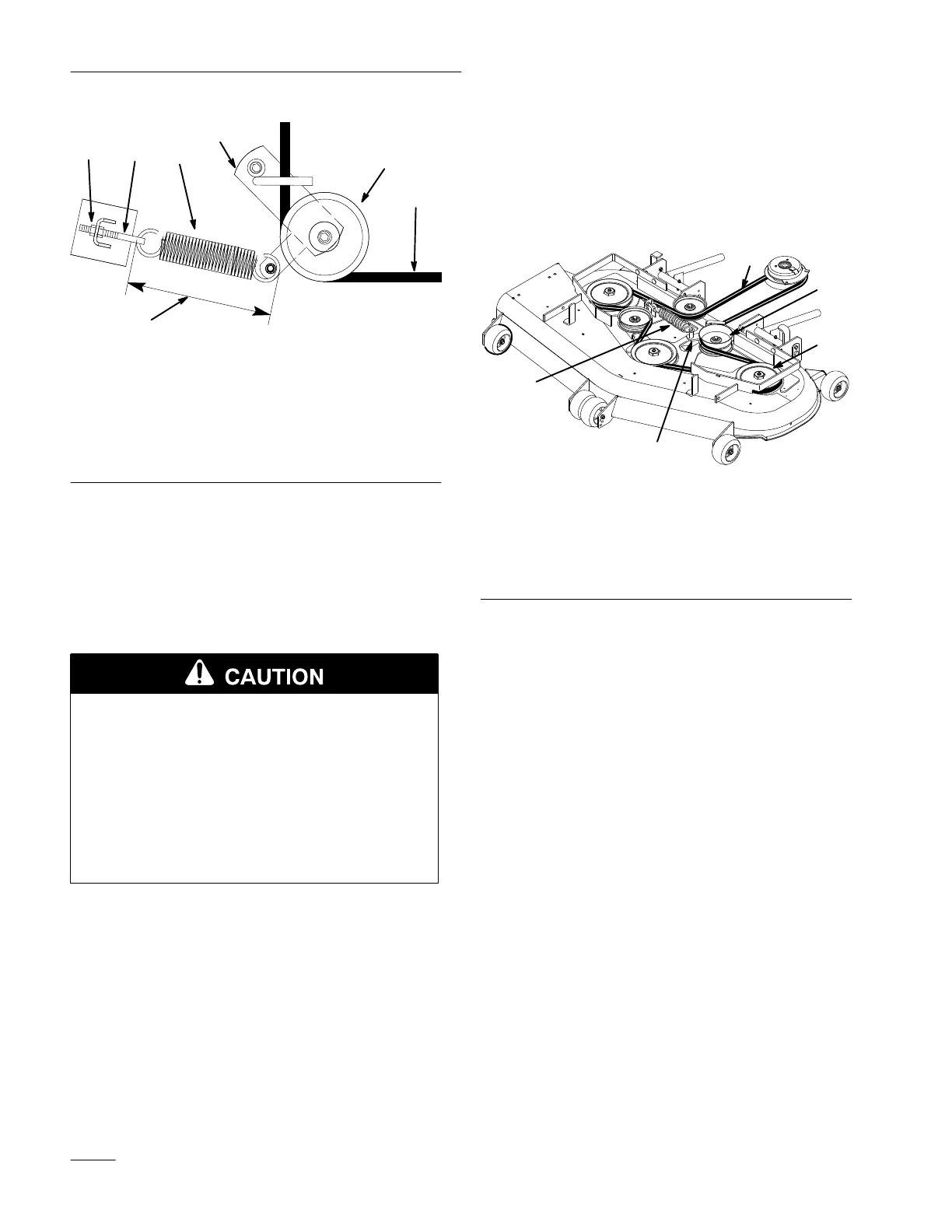
Figure 46
T
op V
iew
1. Outer
Nut
2.
Idler Pulley
3.
Idler Arm
4.
Spring Eye Bolt
5. Spring
6.
9.375
±
.125
(238 mm
±.3 mm)
7. Deck
Belt
4. Remove belt. Start at outside pulley and rotate
off (Fig. 47).
Note: Dot not remove spring from eye bolt.
5. Verify length of push arms. Refer to Adjusting
Push Arms on page 51.
POTENTIAL HAZARD
• Spring is under tension when installed.
WHAT CAN HAPPEN
• Stored spring energy can cause personal
injury.
HOW TO AV
OID THE HAZARD
• Do not remove spring from spring eye bolt.
6. Remove spring loaded idler pulley (Fig. 46).
7. Route new belt through idler arm (Fig. 46).
8. Reinstall idler pulley and route belt onto other
pulleys (Fig. 47).
9. Retighten outer nut on spring eye bolt (Fig. 46).
Note: Check spring length. The spring should
measure 9.375” ± .125” (238 mm ±.3
mm) when installed. Adjust if it does
not (Fig. 46).
10. Install belt covers over outside spindles.
1
2
3
4
5
M-4159
Figure 47
T
op V
iew
1. Deck
Belt
2.
Idler Arm
3.
Outside Pulley
4. Spring
5.
Idler Pulley