Maintenance
56
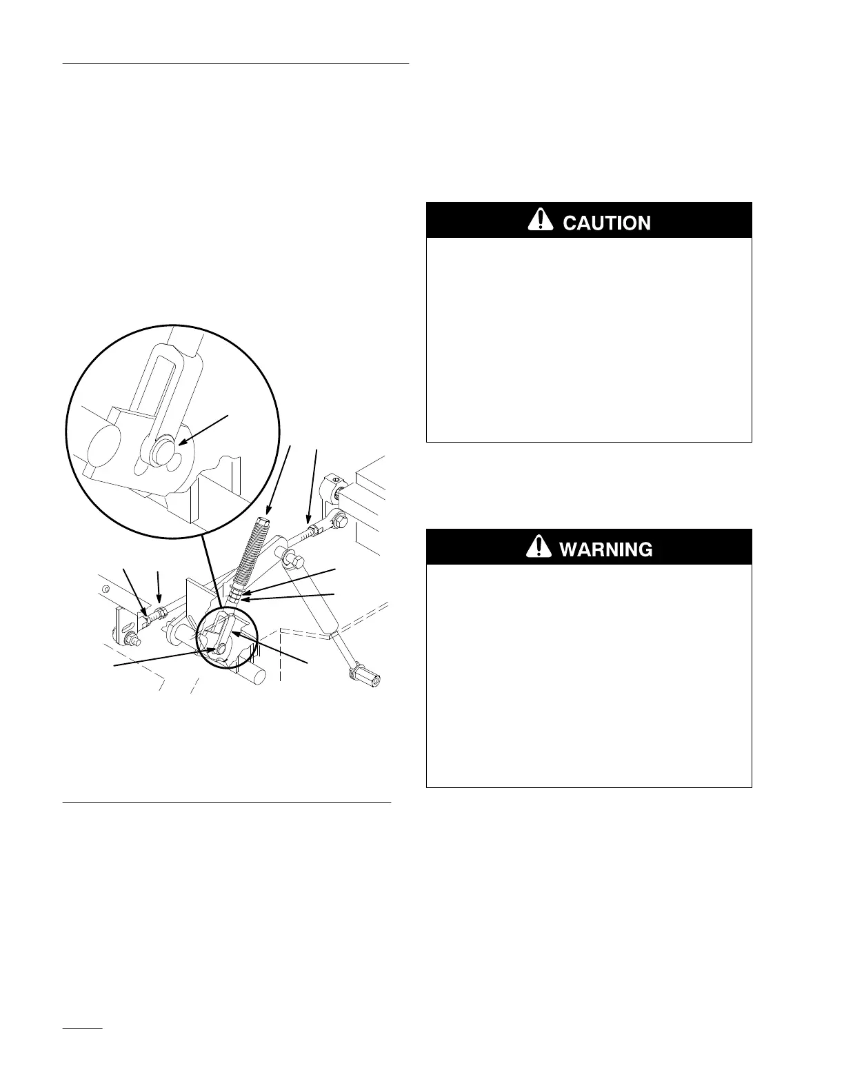
5. Apply slight rearward pressure on the motion
control lever, turn the head of the adjustment
bolt in the appropriate direction until lever is
centered in neutral lock position (keeping
rearward pressure on the lever will keep the pin
at the end of the slot and allow the adjustment
bolt to move the lever to the appropriate position
(Fig. 50).
6. Tighten nut and jam nut.
7. Repeat on opposite side of unit.
1
1
2
6
4 3
2
7
8
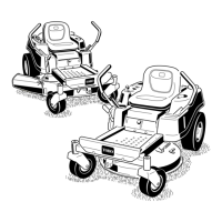
Figure 50
1. Clevis
pin in slot
2. Nut
3.
Nut– Left hand Thread
4. Bolt
5.
Pump rod
6.
Double nuts
7.
Jam Nut
8. Yoke
Adjusting Hydraulic Pump Neutral
Note: Adjust handle neutral first. That has to
be correct before the following
adjustment can be made.
POTENTIAL HAZARD
• Mechanical or hydraulic jacks may not
support machine.
WHAT CAN HAPPEN
• Weight of machine can cause hydraulic
jacks to fail and cause an injury.
HOW TO AV
OID THE HAZARD
• Use jack stands when supporting machine.
• Do not use hydraulic jacks.
1. This adjustment must be made with drive wheels
turning. First raise the frame and block up so
drive wheels can rotate freely.
POTENTIAL HAZARD
• Engine must be running so motion control
adjustment can be performed.
WHAT CAN HAPPEN
• Contact with moving parts or hot surfaces
may cause personal injury.
HOW TO AV
OID THE HAZARD
• Keep hands, feet, face, clothing and other
body parts away from rotating parts,
muffler and other hot surfaces.
2. Slide seat forward, disconnect prop rod and tilt
seat fully forward.
3. Disconnect electrical connector from the seat
safety switch. Temporarily
install a jumper wire
across terminals in the wiring harness connector.
4. Loosen locknut at ball joint on pump control rod
(Fig. 50).