Maintenance
57
Note: The front nut of each rod has left–hand
threads.
5. Start engine, open throttle 1/2 way and release
parking brake. Refer to Starting and Stopping
the Engine, page 24.
6. Adjust pump rod length by rotating double nuts
on rod, in the appropriate direction, until wheel
is still or slightly creeps in reverse (Fig. 50).
7. Move motion control lever forward and reverse,
then back to neutral. Wheel must stop turning or
slightly creep in reverse.
Note: Motion control lever must be in neutral
while making any adjustments.
8. Open throttle to fast. Make sure wheel remains
stopped or slightly creeps in reverse, re-adjust if
necessary.
9. Repeat on opposite side of unit. T
ighten locknuts
against ball joints.
POTENTIAL HAZARD
• Electrical system will not perform proper
safety shut off with jumper wire installed.
WHAT CAN HAPPEN
• Contact with moving parts may cause
personal injury.
HOW TO AV
OID THE HAZARD
• Remove jumper wire from wir
e harness
connector and plug connector into seat
switch when adjustment is completed.
• Never operate this unit with jumper install
and seat switch by passed.
10. Shut off unit. Remove jumper wire from wire
harness connector and plug connector into seat
switch.
11. Reinstall prop rod and lower seat.
Adjustment
Parking Brake
Check parking brake for proper adjustment.
1. Disengage brake lever (lever down).
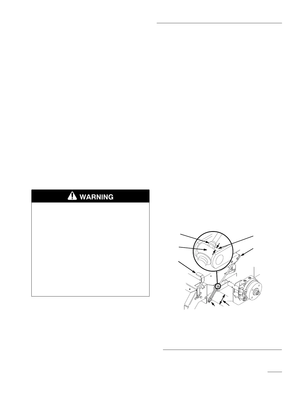
2. Measure the length of the spring. Measurement
should be 2.75” (74 mm) between washers
(Fig. 51).
3. If adjustment is necessary, loosen the jam nut
below the spring and tighten the nut directly
below the yoke (Fig. 51). Turn the nut until the
correct measurement is obtained. Tighten the
two nuts together and repeat on
opposite
side of
unit.
4. Turn nuts clockwise to shorten spring length and
turn counter–clockwise to lengthen the spring.
5. Engage parking brake, lever up.
6. Measure the distance between the trunnion roller
and the collar on brake rod . Measurement
should be 3/16”–1/4” (5–7 mm) (Fig. 51).
7. If adjustment is necessary, loosen the jam nut
directly below the yoke. Turn the bottom
adjusting nuts until the correct measurement is
obtained (Fig. 51). Tighten jam nut at yoke
M-4120
11
2
3
4
7
5
6
Figure 51
1. Brake
lever
2.
Spring 2.75” (74 mm)
3.
Adjusting nuts
4.
Collar on brake rod
5.
3/16”–1/4’ (5–7 mm)
6.
Jam nut and yoke
7. Trunion