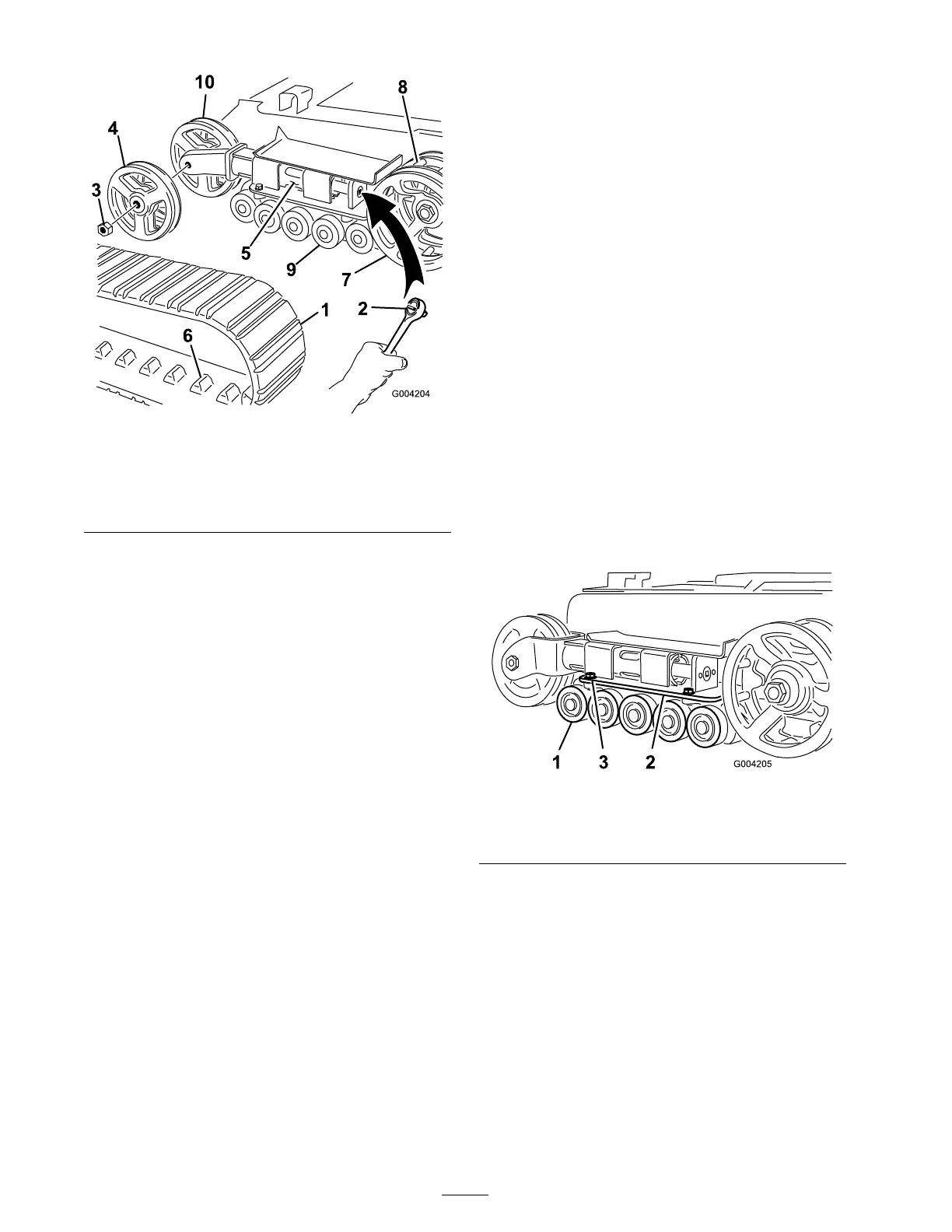
Figure 47
1. Track 6. Track lug
2. 1/2 inch socket 7. Drive sprocket
3. Tension wheel nut 8. Sprocket spacer
4. Outer tension wheel 9. Road wheels
5. Fork tube 10. Inner tension wheel
5. Push the tension wheel to w ard the rear of
the unit to mo v e the tension tube ag ainst the
frame ( Figure 47 ). (If it does not touc h the
frame , contin ue tur ning the tensioning screw
until it does .)
6. R emo v e the n ut securing the outer tension
wheel and remo v e the wheel ( Figure 47 ).
7. R emo v e the trac k ( Figure 47 ).
8. R emo v e the n ut securing the inner tension
wheel and remo v e the wheel ( Figure 47 ).
9. Pull the 4 larg e w ashers out of the 2 wheels , 1
on eac h side of eac h wheel.
10. Clean the old g rease and dir t out of the area
betw een where the w ashers w ere installed and
the bearings inside the wheels , then fill this
area on eac h side of eac h wheel with g rease .
11. Install the larg e w ashers on the wheels o v er
the g rease .
12. Install the inner tension wheel and secure it
with the n ut remo v ed previously ( Figure 47 ).
13. T or que the n ut to 300 ft-lb (407 N ⋅ m).
14. Install the new trac k, ensuring that the lugs in
the trac k fit betw een the spacers in the middle
of the dri v e sproc k et ( Figure 47 ).
15. Install the outer tension wheel and secure it
with the n ut remo v ed previously ( Figure 47 ).
16. T or que the n ut to 300 ft-lb (407 N ⋅ m).
17. T ur n the tensioning screw counter -cloc kwise
until the distance betw een the tension n ut and
the bac k of the tension tube ( Figure 44 ) is
2-3/4 inc hes (7 cm).
18. Align the closest notc h in the tension screw to
the loc king bolt hole and secure the screw with
the loc king bolt and n ut.
19. R e peat ste ps 2 through 18 to re place the other
trac k.
20. Lo w er the traction unit to the g round.
Maintaining the Road Wheels
Chec k and g rease the road wheels ev er y 250
operating hours or yearly .
1. R emo v e the trac ks; refer to R e placing the
T rac ks .
2. R emo v e the 4 bolts securing eac h lo w er trac k
guide whic h contains the road wheels , and
remo v e them ( Figure 48 ).
Figure 48
1. Road wheels
3. Track guide bolts (only two
shown)
2. Lower track guide
3. R emo v e the snap ring and cap from a road
wheel ( Figure 49 ).
40
 Loading...


