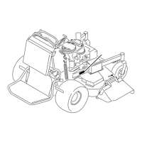
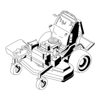
Figure80
1.Blade2.Balancer
InstallingtheBlades
1.Installthebladeontothespindleshaft(Figure81).
Important:Thecurvedpartoftheblademust
bepointingupwardtowardtheinsideofthe
mowertoensurepropercutting.
2.Installthespringdiskandbladebolt.Thespring
diskconemustbeinstalledtowardthebolthead
(
Figure81).Torquethebladeboltto85-110ft-lb
(115-150N-m).
Figure81
1.SailAreaofBlade
4.BladeBolt
2.Blade
5.ConeT owardsBoltHead
3.SpringDisk
CorrectingtheMowerQuality
ofCut
Ifonedeckbladecutslowerthantheother,correctas
follows.
Note:Tireairpressureiscriticalintheseprocedures.
Makesurethereartireshavecorrectpressure.
1.DisengagethePTOandsettheparkingbrake.
2.Stoptheengine,removethekey,andwaitforall
movingpartstostopbeforeleavingtheoperating
position.Disconnectthesparkplugwire(s)from
thesparkplug(s).
3.Adjustthetirepressureinthereartiresto12-14psi
(83-97kPa).
4.Checkthatthebladesandspindleshaftsarenot
bent.RefertoCheckingforBentBlades.
5.Settheheight-of-cuttothe3inch(7.6cm)position.
RefertoAdjustingtheHeight-Of-CutinOperation.
6.Performthestepsinthefollowingproceduresin
order.
CheckingtheMowerDeckSide-to-Side
Height
1.Adjustthereartirepressure.
2.Ensurethebladesarenotbent.RefertoChecking
forBentBlades.
3.Positionthebladesside-to-side.MeasureatBand
Clocationsfromalevelsurfacetothecuttingedge
ofbladetips(
Figure82).
Figure82
1.Measurefromalevel
surface
2.MeasurebladeatpointsB
andC
4.ThedifferencebetweenmeasurementsBandC
shouldbenomorethan1/4inch(6mm).IIfitis
notcorrect,proceedtoChangingtheMowerDeck
Side-to-SideHeight.
ChangingtheMowerDeckSide-to-Side
Height
Changingtheside-to-sideheightisdonebyadjusting
thereartirepressureandU-platesonthesideofthe
enginedeck.
55

 Loading...
