EasyManua.ls Logo

Toro Mini 8 Series - User Manual

Toro Mini 8 Series
2 pages
Print Icon
To Next Page IconTo Next Page
Loading...
The Mini 8 Rotor is designed for residential and light commercial
installations. It comes in three sizes, 4" pop up, 6" pop up and 12" pop up.
Nozzling Up The System
The 1.5 GPM nozzle comes pre-installed from the factory. A nozzle tree
consisting of four additional nozzles is provided with each rotor (
Figure 1).
Please see the nozzle performance chart for flow rates. By using various
combinations of nozzle flow rates, you can balance the sprinklers to
achieve approximately the same precipitation rates.
Every case of Mini 8 product contains two Mini 8 rotor keys. The Mini 8 key
is used to pull up the riser, to remove the nozzle, to reduce the radius and
to adjust the arc (
Figure 2).
To Extract/Insert A Nozzle
Use the winged portion of the key to pull the riser up in order to access the
nozzle orifice. Insert the key into the pull-up hole (
Figure 3), turn it 90˚, and
pull up. Hold the riser in the pulled up position.
Using the end of the key, turn the radius adjustment screw
counterclockwise until it clears the top of the nozzle. See Figure 4A.
Insert the key into the nozzle right side slot with the pointed end of the key
facing upwards. Use the point to extract the nozzle out. See
Figure 4B.
To install a nozzle, press the nozzle into the nozzle socket
(
Figure 5A). Turn the radius adjustment screw clockwise to its desired
location ensuring that it is in a position to hold the nozzle in place even if
radius reduction is not required (
Figure 5B).
To Set The Arc
The Mini 8 rotor arc is pre-set from the factory at 90˚.
The Mini 8 rotor has a fixed LEFT stop. To find the left stop position,
rotate the nozzle turret clockwise (to the right) until it stops, then rotate the
nozzle turret all the way back to the left.
To increase the arc, insert the key into the arc adjuster shown in Figure 6.
Hold the turret in place while turning the tool clockwise. Keep turning until
the arc indicator arrow points to the desired arc angle.
As an example indicated in Figure 7, the arc is set to 270˚. The sprinkler
will then water from the left stop and rotate clockwise (see
Figure 8) until
270˚, the adjusted right stop, is reached. The sprinkler will then return back
to the left stop and repeat the cycle.
To decrease the arc, insert the key into the arc adjuster. Hold the turret in
place while turning the tool counter clockwise. Keep turning until the arrow
points to the desired arc.
To adjust the arc while the rotor is running, turn the turret gently in the
direction that it is spraying. Once the left stop has been located, follow the
directions above to increase or decrease the arc.
To line up the left stop with landscape features which define the left side of
the irrigated arc, simply turn the housing cannister and point the left stop
towards the desired direction. You may also pull the riser up with the key
and rotate the LOWER portion of the riser until the left stop is at the
desired position.
DO NOT rotate the TOP portion of the riser.
Installation Tips
The Mini 8 rotor should be installed with
the cap at the finished grade. It is not
designed to be installed below grade. See
Figure 9.
The radius adjustment screw can be used
to reduce the radius throw by up to 25%.
You should note that this does not reduce
the flow of the nozzle.
Screen Maintenance
The screen can be accessed through the
bottom of the riser. Remove the cap of the
Mini 8 and lift the riser assembly out of the
housing cannister. If plugged, the screen can
be removed, cleaned, and re-inserted into
the riser.
Mini 8 Nozzle Performance
For Product Inquiries:
The Toro Company
5825 Jasmine Street
Riverside, CA 92502-0489
Tel: (909) 688-9221
(800) 225-2839
Mini 8, Gear Driven Sprinkler
Users Guide
.75
GPM
1.0 GPM
1.5 GPM
2.0 GPM
1.0
.75
1.5
3.0
2.0
3.0 GPM
Figure 1 Figure 2
Nozzle Tree
Mini 8
Rotor Key
Arc Adjuster
Pull-Up
Keyhole
Arc Angle
Indicator
Radius Adjustment/
Nozzle Retention
Screw
Figure 3 Figure 4 Figure 5
Figure 6 Figure 7 Figure 8
Increase
Decrease
Left Stop Position
Angle Indicator
Points To 270˚
Left Stop
Position
Adjustable
Right Stop
Position
(270˚)
Figure 9
A
B
A
B
Figure 9
Screen
© 2002 The Toro Company Form Number 373-0266 Rev. A
4" Pop Up
6" Pop Up
12" Pop Up
Nozzle
(Gallons)
0.75
1.0
1.5
2.0
3.0
Pressure
(PSI)
30
40
50
30
40
50
30
40
50
30
40
50
30
40
50
Flow
(GPM)
0.8
0.9
1.2
1.1
1.3
1.5
1.2
1.4
1.6
1.4
1.7
2.0
2.3
2.6
3.0
Radius
(Feet)
19
20
21
22
23
24
26
28
30
30
31
32
33
34
35
Pressure
(kPa)
207
276
345
207
276
345
207
276
345
207
276
345
207
276
345
Flow
(L/M)
3.03
3.41
4.54
4.16
4.92
5.68
4.54
5.30
6.06
5.30
6.43
7.57
8.71
9.84
11.36
Flow
(M
3
/H)
0.2
0.2
0.3
0.2
0.3
0.3
0.3
0.3
0.4
0.3
0.4
0.5
0.5
0.6
0.7
Radius
(Meters)
5.8
6.1
6.4
6.7
7.0
7.3
7.9
8.5
9.1
9.1
9.4
9.8
10.1
10.4
10.7
Question and Answer IconNeed help?

Do you have a question about the Toro Mini 8 Series and is the answer not in the manual?

Summary

Nozzling Up The System

To Set The Arc

Screen Maintenance

Mini 8 Nozzle Performance

To Extract;Insert A Nozzle

Installation Tips

For Product Inquiries

Overview

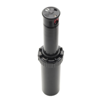
The Mini 8, Gear Driven Sprinkler is a device designed for both residential and light commercial irrigation needs. It is available in three sizes: 4-inch, 6-inch, and 12-inch pop-up models, offering flexibility for various landscape requirements.

Function Description

The primary function of the Mini 8 rotor is to distribute water over a specified area. It comes with a pre-installed 1.5 GPM nozzle, and a nozzle tree containing four additional nozzles is provided with each rotor. These nozzles allow users to customize flow rates, enabling them to balance sprinklers and achieve consistent precipitation rates across the irrigated area. The rotor's arc is pre-set at 90° from the factory, but it can be adjusted to suit specific landscape needs.

Usage Features

The Mini 8 rotor is designed for ease of use and adjustment. Two Mini 8 rotor keys are included with every product, serving multiple purposes: pulling up the riser, removing nozzles, reducing the radius, and adjusting the arc.

Nozzle Installation and Removal:

To access the nozzle orifice, the riser must be pulled up. This is done by inserting the winged portion of the key into the pull-up hole, turning it 90°, and pulling up. Once the riser is in the pulled-up position, the radius adjustment screw can be turned counterclockwise until it clears the top of the nozzle. To extract a nozzle, the pointed end of the key is inserted into the nozzle's right side slot, facing upwards, and used to pull the nozzle out. For installation, a new nozzle is pressed into the nozzle socket, and the radius adjustment screw is turned clockwise to secure the nozzle in place. It's important to ensure the screw is positioned to hold the nozzle even if radius reduction is not required.

Arc Adjustment:

The Mini 8 rotor has a fixed LEFT stop. To locate this stop, the nozzle turret is rotated clockwise until it stops, then rotated all the way back to the left. To increase the arc, the key is inserted into the arc adjuster. While holding the turret in place, the tool is turned clockwise until the arc indicator arrow points to the desired arc angle. For example, if the arc is set to 270°, the sprinkler will water from the left stop and rotate clockwise until it reaches the adjusted right stop (270°), then return to the left stop and repeat the cycle. To decrease the arc, the key is inserted into the arc adjuster. While holding the turret in place, the tool is turned counter-clockwise until the arrow points to the desired arc. Arc adjustments can also be made while the rotor is running by gently turning the turret in the direction it is spraying. Once the left stop is located, the user can follow the same increase or decrease arc adjustment procedures. To align the left stop with specific landscape features, the housing canister can be turned to point the left stop towards the desired direction. Alternatively, the riser can be pulled up with the key, and the LOWER portion of the riser can be rotated until the left stop is in the desired position. It is crucial NOT to rotate the TOP portion of the riser during this process.

Radius Reduction:

The radius adjustment screw can be used to reduce the radius throw by up to 25%. It's important to note that this adjustment does not reduce the flow of the nozzle.

Installation Tips:

The Mini 8 rotor should be installed with its cap at the finished grade. It is not designed for below-grade installation.

Maintenance Features

Screen Maintenance:

The screen, which is crucial for preventing debris from entering the sprinkler mechanism, is accessible through the bottom of the riser. To access it, the cap of the Mini 8 must be removed, and the riser assembly lifted out of the housing canister. If the screen is plugged with debris, it can be removed, cleaned, and re-inserted into the riser. This ensures optimal performance and longevity of the sprinkler.

Toro Mini 8 Series Specifications

General IconGeneral
Spray PatternAdjustable
ModelMini 8 Series
CompatibilityToro irrigation systems
MaterialPlastic
ColorBlack
TypeSprinkler

Related product manuals