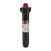
SPECIFICATIONS AND SERVICE INSTRUCTIONS
Specifications • Pressure Range: 25–75 psi (1.8–5.3 kg/cm
2
) (172.4–517.1 kPa) • Nozzle Trajectory: 7°–25°
• Optimum Pressure: 50 psi (3.5 kg/cm
2
) (344.8 kPa) • Inlet Size:
3
/4"
• Arc Range: 40°–360° (Part Circle Models)
Flow Adj. Pressure Radius Flow Precipitation Rate*
GPM PSI feet GPM ▲ in/hr ■ in/hr
1 50 31 1.34 0.13 0.13
1.5 50 33 1.67 0.14 0.15
2 50 37 2.63 0.18 0.19
3 50 38 3.44 0.22 0.23
4 50 41 4.56 0.25 0.26
4.5 50 42 5.14 0.27 0.28
6 50 47 6.90 0.29 0.30
8 50 48 8.41 0.34 0.35
9 50 48 9.40 0.37 0.39
* Precipitation rates are calculated at 55% of diameter for triangular spacing and 50% of diameter for square spacing.
Flow Adj. Pressure Radius Flow Precipitation Rate*
l/mn kg/cm
2
kPa meters l/mn m
3
/hr ▲ mm/hr ■ mm/hr
4 3.5 344.8 9.4 5.0 0.30 3.26 3.42
6 3.5 344.8 10.0 6.3 0.38 3.59 3.76
8 3.5 344.8 11.2 10.0 0.60 4.53 4.74
11 3.5 344.8 11.5 12.9 0.78 5.57 5.84
15 3.5 344.8 12.4 17.2 1.03 6.35 6.65
17 3.5 344.8 12.7 19.3 1.16 6.82 7.14
23 3.5 344.8 14.3 26.0 1.56 7.31 7.66
30 3.5 344.8 14.6 31.6 1.90 8.54 8.95
34 3.5 344.8 14.6 35.4 2.12 9.54 10.00
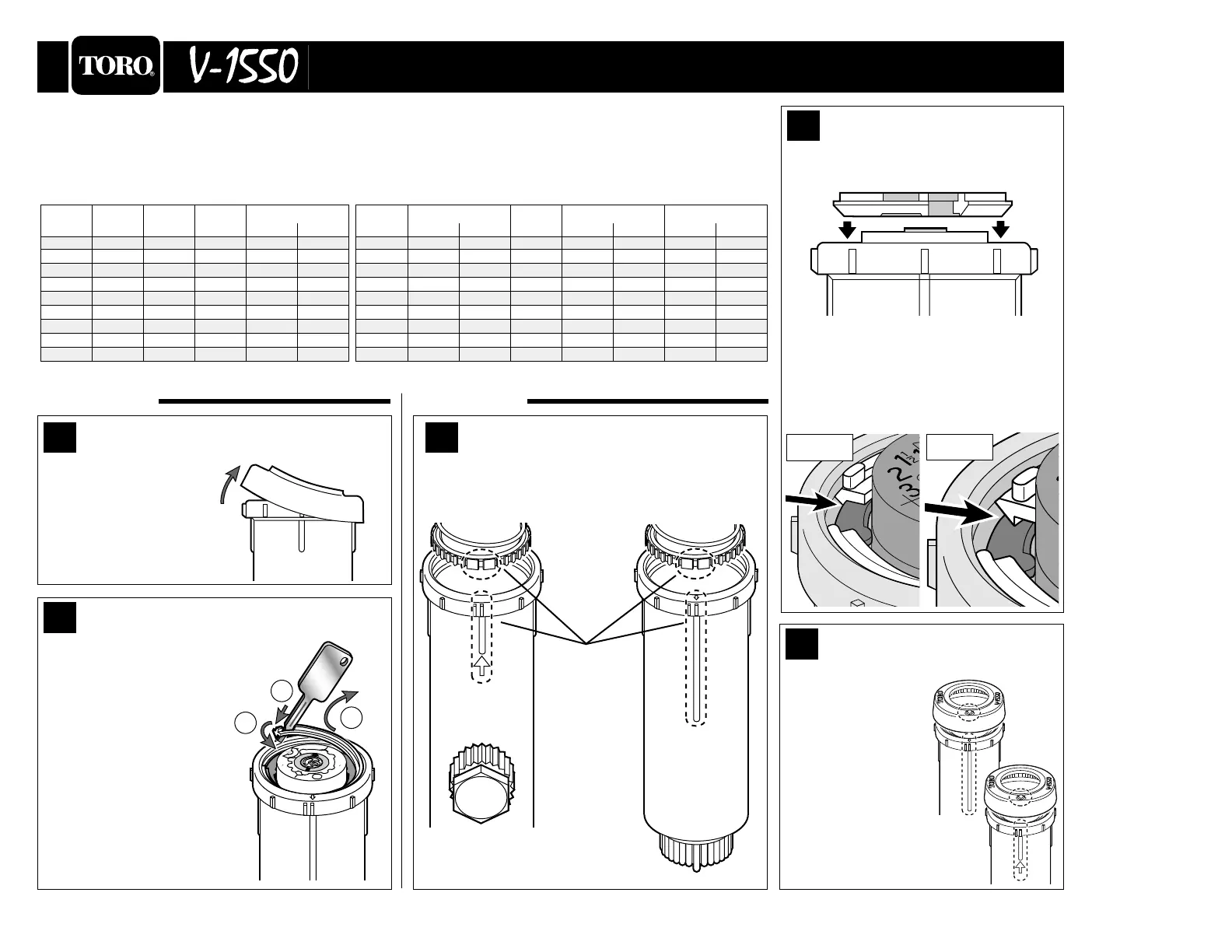
Sprinkler Performance at 25° Trajectory
Install Snap Ring
1. Place snap ring into body with beveled
side down.
CAUTION: Snap ring must be properly
installed in body groove and with gray
interlocking ring as shown to ensure
retention of sprinkler assembly.
2
Right Wrong
Install Rubber Cover
1. For part circle
sprinkler, align
arrow on cover with
alignment keys on
body as shown.
2. Push cover onto lip
of body to secure.
3
Disassembly
Reassembly
Remove Snap Ring
1. Insert Toro tool into snap ring slot until
gray interlocking ring beneath snap ring
is pressed down.
2. With twisting motion, disen-
gage snap ring from body.
3. Twist snap ring out.
4. Remove sprinkler assembly
from body.
2
Remove Rubber Cover
1. Grasp lower edge of
rubber cover and pull
away from lip of body
as shown.
1
1
2
3
Install Sprinkler Assembly
1. To maintain left side arc alignment of part circle
sprinkler, position alignment keys as shown.
2. Insert sprinkler assembly into body.
1
6
4
34
30
23
8
1
1
1 5
1 7
1
1
2
3
4
4
6
8
9
1
2
1
2
GPM
-
+
A
R
C
-
+
R
A
D
I
U
S
F
L
W
O
A
D
J
l/m
n
© 2000 THE TORO COMPANY • IRRIGATION DIVISION FORM NO.
PRINTED IN U.S.A. 368-0095 REV. E
Alignment
Keys
V-1550-12
V-1550-4
V-1550-12
V-1550-4