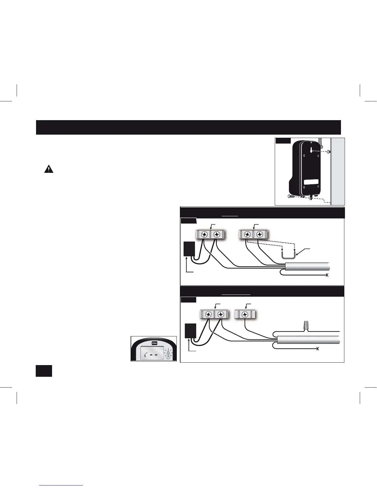
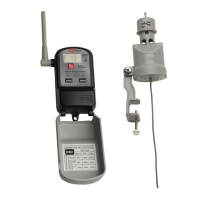
1. Attach the receiver next to the irrigation controller using the two
stainless steel screws provided (Fig. 2). Where appropriate, foam tape
(provided) can be used to attach the receiver.
Warning: Disconnect 24 VAC power to controller before connecting
receiver. DO NOT connect receiver to 110/220 VAC (house current).
3PVUFUIFSFDFJWFSDBCMFJOUPUIFDPOUSPMMFSDBCJOFU
Note: If your controller has a sensor bypass switch, make sure
JUJTTFUUPFOBCMFUIFTFOTPS3FGFSUP
the irrigation controller’s user guide
for specifics.
3. Connect the receiver per the applicable
wiring diagram (Fig. 3a or 3b).
*Note'PSB/PSNBMMZ0QFOTFOTPS
application, connect the Yellow wire in
place of the Brown wire.
"QQMZQPXFSUPDPOUSPMMFS The receiver
will appear as shown below when power
is first applied. If the display and LED are
OPUPODIFDLUIF3FEXJSFDPOOFDUJPOT
Step 2 - Install and Connect the Receiver
4
Remove
Jumper
Red
Red
Brown
White
Receiver Cable
24 VAC
Controller with Sensor Terminals
Yellow (see *Note)
Yellow (not used)
Transformer
(power to the controller)
Fig. 3a
Fig. 2
Transformer
(power to the controller)
Fig. 3b
Controller without Sensor Terminals
Brown
White
Red
Red
Valve
Common
from Field
Receiver Cable
24 VAC
Valve Common
Rain Sensor Terminal