Operation
8
Adjusting
the Height-of-Cut
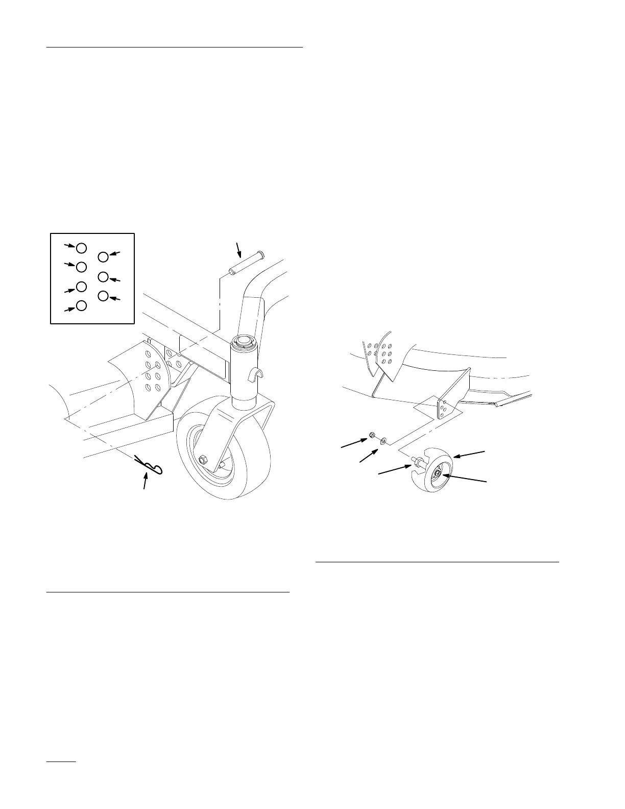
The height-of-cut is adjustable from 2” to 5” (51 to
127 mm) in 1/2-inch (13 mm) increments by
relocating the clevis pins in different hole locations in
brackets at each corner of the cutting unit (Fig. 9).
Stop the engine before adjusting the height-of-cut.
Note: All four pins must be in the same hole
location for even cutting.
8
9
1
3
5
7
2
4
6
Figure 9
1. 2”
(51 mm) Cut Height
2.
2-1/2” (64 mm) Cut Height
3.
3” (76 mm) Cut Height
4.
3-1/2” (89 mm) Cut Height
5.
4” (102 mm) Cut Height
6.
4-1/2” (1
14 mm) Cut
Height
7.
5” (127 mm) Cut Height
8.
Clevis Pin
9.
Hairpin Cotter
Adjusting
Gage Wheels
The gage wheels must be adjusted in the proper hole
location for each height-of-cut position.
1. After adjusting height-of-cut remove nut and
washer while holding stud with wrench
(Fig. 10).
Note: Do not remove the wheel nut and
washer (Fig. 10).
2. Select a hole position so the gage wheel is 3/8”
(9.5 mm) off the ground for the height-of-cut to
be used (Fig. 10).
3. Reinstall the stud nut and washer (Fig. 10).
4. Repeat adjustment on other gage wheels.
m–4123
1
2
3
4
5
Figure 10
1. Gage
Wheel
2. Stud
3. Washer
4. Nut
5.
Wheel nut and washer
.
Do Not Remove.