3
Assembling the Brush Kit
to the Machine
Parts needed for this procedure:
2 Lower brush bracket
4
Self-tapping, ange-head screw (6 x 20 mm)
2
Capscrew (6 x 20 mm)
4
W asher (6 mm)
2
Locknut (6 mm)
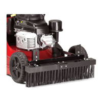
Removing the Wheels
1. Remove the ange locknut (3/8 inch) that
secures the wheel to the axle, and remove the
wheel ( Figure 5 ).
g284602
Figure 5
1. Axle
3. Flange locknut (3/8 inch)
2. Wheel
2. Repeat step 1 for the wheel at the other side of
the machine.
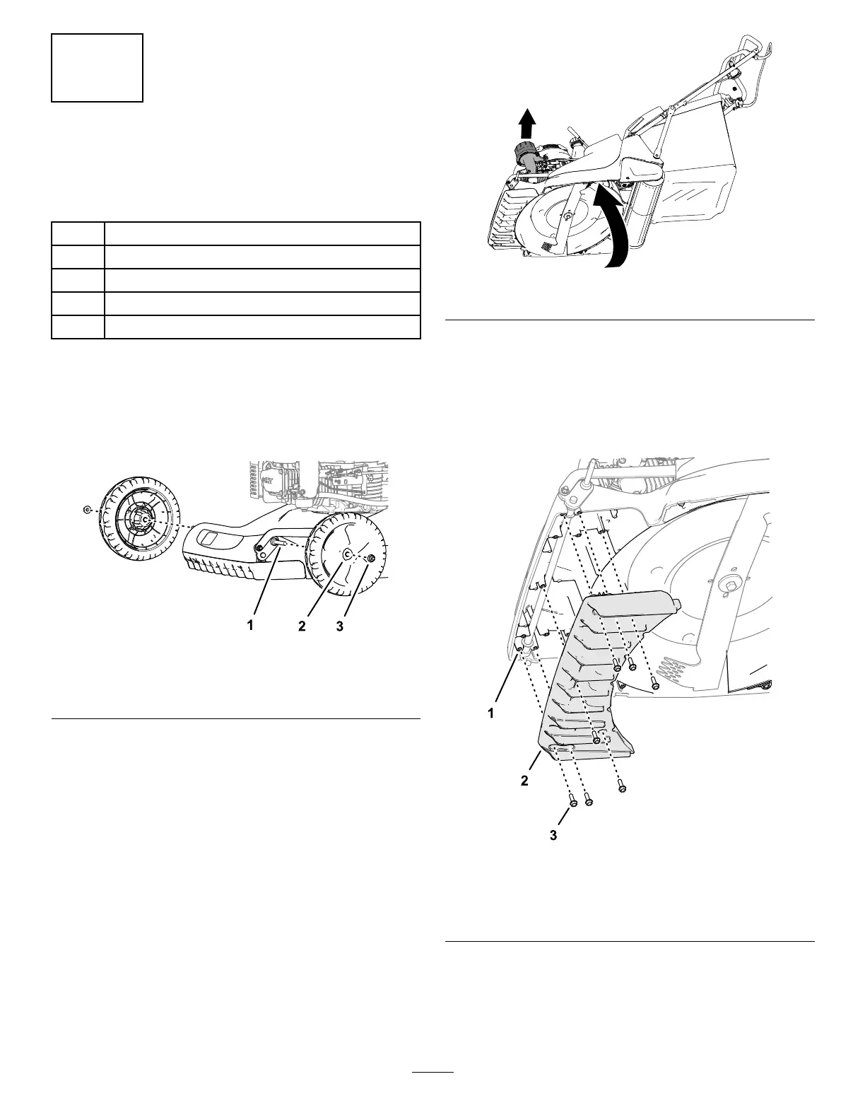
Removing the Front Fins
1. T ip the machine onto its side with the air lter or
height-of-cut lever up ( Figure 6 ).
g283871
Figure 6
2. Remove the 7 self-tapping, ange-head screws
(6 x 20 mm) that secure the front ns to the
supports of the mower deck, and remove the
front ns ( Figure 7 ).
Note: Y ou will not use these front ns with the
groomer brush kit.
g284601
Figure 7
1. Support (front n—mower
deck)
3. Self-tapping, ange-head
screw (6 x 20 mm)
2. Front ns
5

 Loading...