g285247
Figure 16
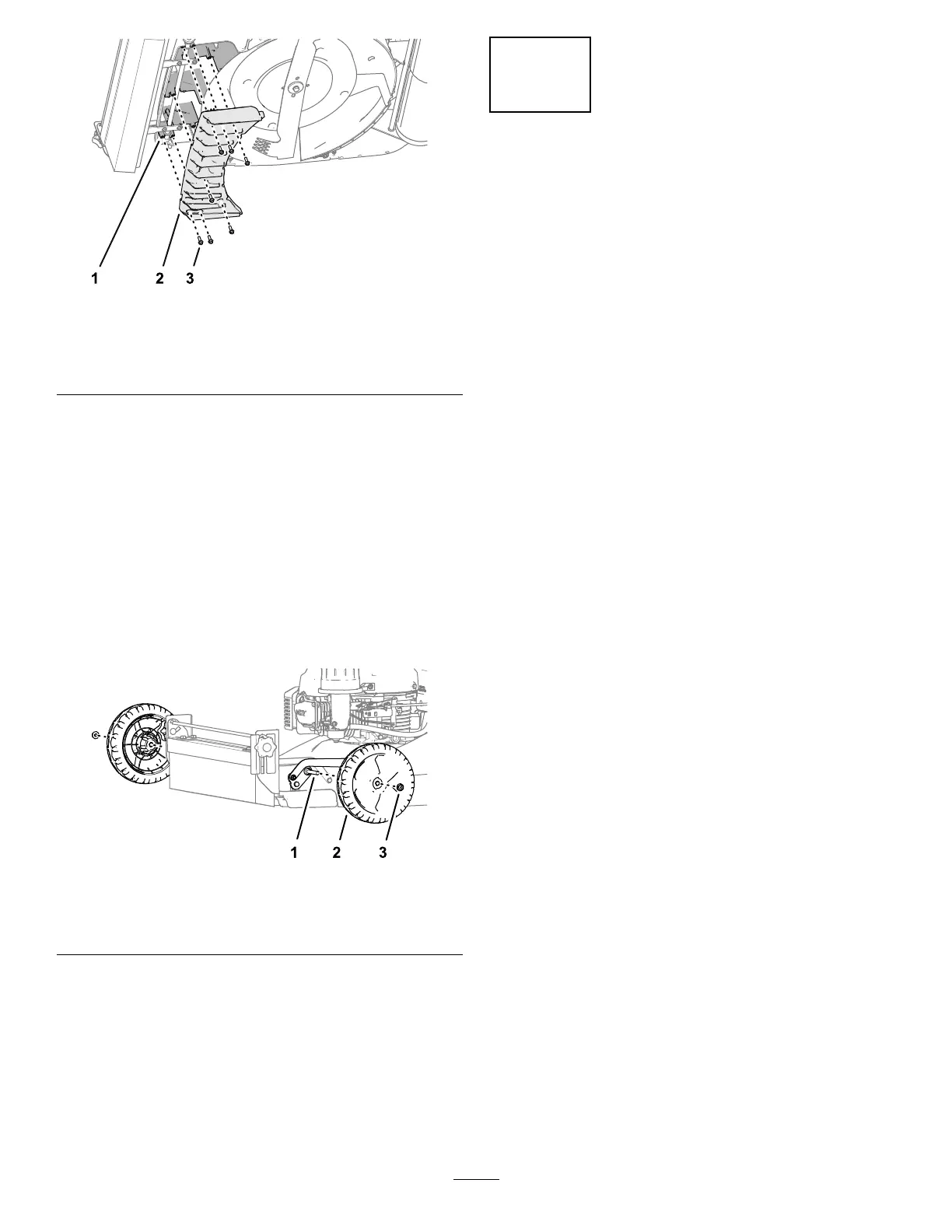
1. Support (front n—mower
deck)
3. Self-tapping, ange-head
screw (6 x 20 mm)
2. Front ns
2. Assemble the front ns to the mower deck
( Figure 16 ) with the 7 self-tapping, ange-head
screws (6 x 20 mm) that you removed in
Removing the Front Fins ( page 5 ) .
3. T ighten the self-tapping, ange-head screws.
Assembling the Wheels to the
Machine
1. Assemble a wheel onto the axle with the ange
locknut (3/8 inch) that you removed in Removing
the Wheels ( page 5 ) .
g284727
Figure 17
1. Axle
3. Flange locknut (3/8 inch)
2. Wheel
2. T ighten the locknut.
3. Repeat steps 1 and 2 for the wheel at the other
side of the machine.
6
Finishing the Kit Installation
No Parts Required
Procedure
Add fuel to the fuel tank or battery packs to the battery
compartment; refer to the Operator ’ s Manual for your
machine.
9

 Loading...