EasyManua.ls Logo

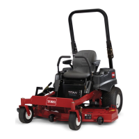
Toro Titan Z5200 - Component Identification and Diagrams; Control Panel and Height Markings; Belt Routing Diagrams

Toro Titan Z5200
52 pages
To Next Page IconTo Next Page
To Previous Page IconTo Previous Page
Loading...
14
109-6029
1
2
3
2
1
3
2
1
3
4
5
6
7
8
9
1. Read the Operator’s
Manual.
2. Rotate the drive release
knob to loosen, slide the
knob, and tighten.
3. Push the machine.
PART NO. 109-6008
LOCATION: Next to Drive
Release
1. Engine – stop
2. Engine – run
3. Engine – start
4. Power take-off
(PTO), Blade control
switch.
5. Read Operator’s
Manual
6. Throttle - fast
7. Choke – on
8. Throttle – slow
9. Choke – off
PART NO. 109-6029
LOCATION: On Control Panel
PART NO. 109-6014
LOCATION: RH Side of
Seat Box
PART NO. 109-6035
LOCATION: Left Rear Edge of Deck
1. Read Operator’s
Manual.
2. Remove the ignition
key and read the
instructions before
servicing or
performing
maintenance.
3. Height of cut.
PART NO. 109-6036
LOCATION: Top of Deck Near Washout Port
TRACTION DRIVE
BELT ROUTING
DECK DRIVE
BELT ROUTING
LOCATION: Blades

Table of Contents

Other manuals for Toro Titan Z5200

Related product manuals