MOWER
6 - 16 XL Lawn Tractor Service Manual
8. Move the cable out of the way and lay inside
frame rail so it can not get caught in drive belts or
pulleys.
Figure 228
1801
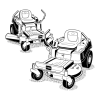
9. Remove the bolts and lock nuts and pull the two
mower pivot mount brackets down from the front
axle (Figure 229).
Figure 229
m-4630
10. Remove the hairpin cotter and washer from the
end of the long rod (Figure 230). Slide the rod out
of the mower mount.
11. Remove the hairpin cotter and washer at the
mower leveling bracket (Figure 230). Slide the
bracket off the mounting pin. Re-install the washer
and hairpin cotter for storage.
12. Rotate the leveling bracket up, toward the frame,
and hook the long rod into one of the holes to
store. Secure long rod with washer and hairpin
cotter.
13. Repeat steps 10-12 on the opposite side of the
mower.
14. Move the height-of-cut lever (deck lift) into the “D”
notch. Hook lift assist spring onto retaining bolt for
storage (Figure 227).
Note: Do not install lift assist spring if rear tire
chains are to be installed.
Figure 230
1805
(A) Blade Control (PTO Cable)
(B) Z End
(C) Idler Arm
(D) Jam Nut
(E) Mounting Bracket
(A) Pivot Mount Bracket
(B) Bolt 5/16-18 x 2-1/2”
(C) Lock Nut
(A) Hairpin Cotter & Washer
(B) Long Rod
(C) Leveling Bracket
(D) Mower Mount
 Loading...