ControlsSystem
Maintenance
AdjustingtheControl-Handle
Position
Thereare2heightpositionsforthecontrollevers—highand
low .Removetheboltstoadjusttheheight.
1.Disengagetheblade-controlswitch(PTO),movethe
motion-controlleverstotheNEUTRAL-LOCKposition,
andsettheparkingbrake.
2.Stoptheengine,removethekey,andwaitforallmoving
partstostopbeforeleavingtheoperatingposition.
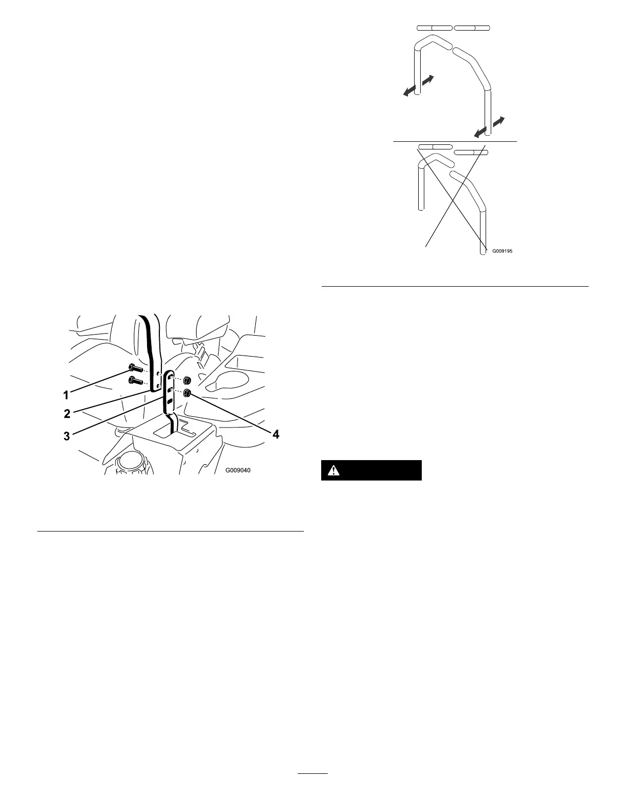
3.Loosentheboltsandangenutsinstalledinthelevers
(Figure65).
4.Aligntheleversinthefront-to-rearpositionbybringing
theleverstogethertotheNEUTRALposition,slidethem
untiltheyarealigned,andtightenthebolts(Figure66).
Figure65
1.Bolt
3.Controllever
2.Handle4.Nut
Figure66
5.Iftheendsofthelevershitagainsteachother,refer
toAdjustingtheMotion-ControlNeutral-LockPivot
(page50).
AdjustingtheMotion-Control
Linkage
Locatedoneithersideofthefueltank,belowtheseatarethe
pump-controllinkages.Rotatingthepumplinkagewitha
1/2inchwrenchallowsne-tuningadjustments,sothatthe
machinedoesnotmoveinneutral.Anyadjustmentsshould
bemadeforneutralpositioningonly.
WARNING
Theenginemustberunningandthedrivewheels
mustbeturning,sothemotion-controladjustment
canbeperformed.Contactwithmovingpartsor
hotsurfacesmaycausepersonalinjury.
Keepyourngers,hands,andclothingclearof
rotatingcomponentsandhotsurfaces.
1.Priortostartingtheengine,pushthedeck-liftpedal,
removetheheight-of-cutpin,andlowerthedeckto
theground.
2.Raisetherearofmachineupandsupportwithjack
stands(orequivalentsupport)justhighenoughto
allowthedrivewheelstoturnfreely.
3.Movetheseattothefurthestrearpositiontoexpose
thefrontnuts.
4.Loosenthefrontnuts.
Note:Youdonotneedtoremovethenuts.
5.Movetheseattothefurthestforwardpositionto
exposetherearnuts.
48
 Loading...