159
The T-1 Notebook : Reference & Guide
158
The T-1 Notebook : Reference & Guide
NOTESNOTES
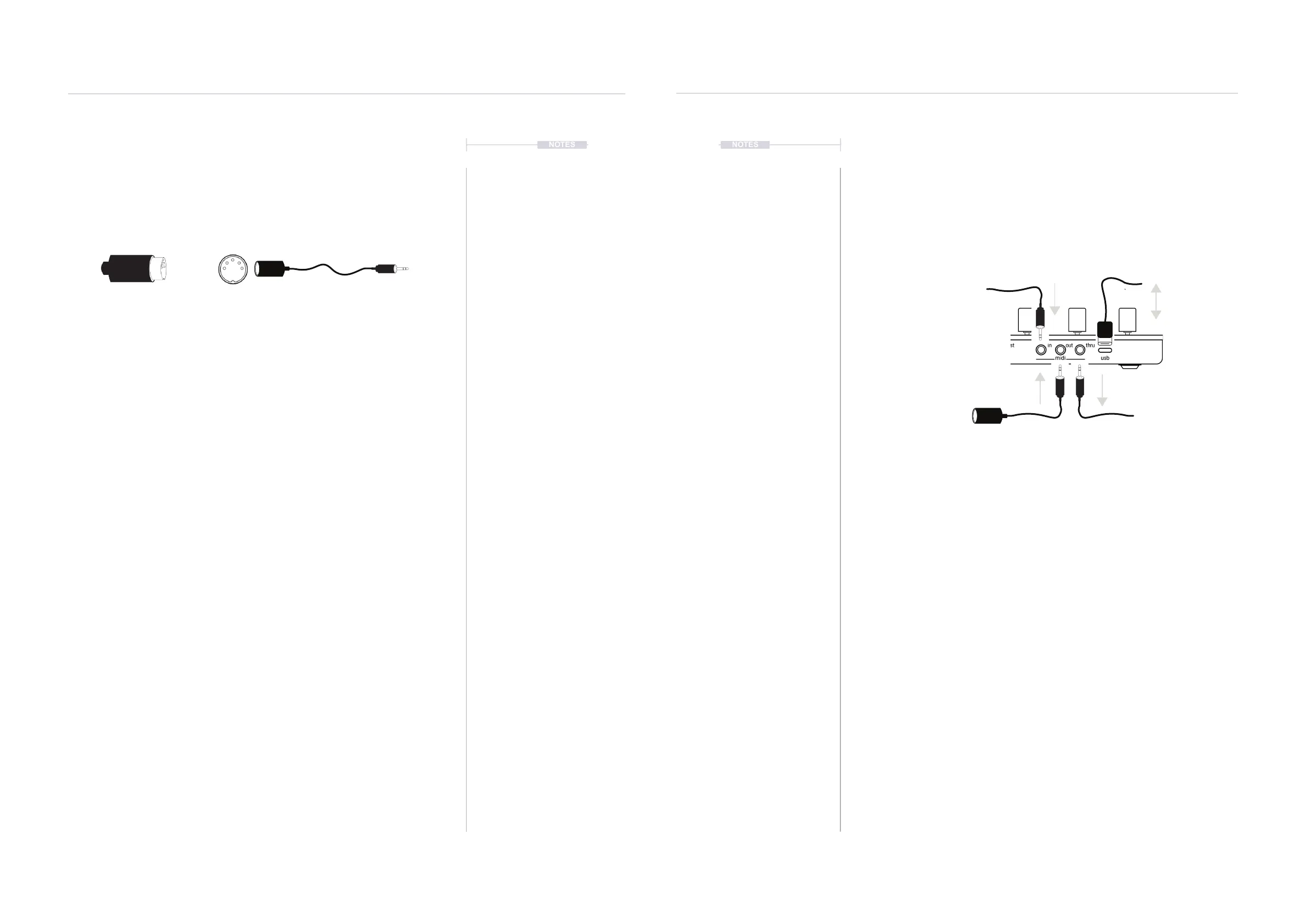
8.2 MIDI Hardware Connections
The rear of T-1 is the location for the input / output connections for external
gear. These can be congured within T-1 but act as the physical interface
between other hardware and software systems.
MIDI OUT
Transmits all MIDI sequencing and control information to a connected
device, system or application. For example a T-1 sequence will control a
MIDI synth module.
MIDI IN
T-1 receives MIDI information which can be directed straight out to MIDI
Thru port or can be processed by T-1 internal MIDI FX Track functions
before sending to the MIDI Out port. This is a unique and creative way to
use T-1 as a MIDI processor when sequencing on another device.
MIDI THRU
Transmits all MIDI information received on the MIDI input port to the MIDI
Thru output. T-1 does not affect the incoming MIDI and Thru is a replication
of MIDI In data. This is default behaviour but can be set as a second MIDI
Out in the T-1 Cong settings.
MIDI USB
Transmits and receives MIDI from an external device. The USB connector
also acts as T-1 power source.
MIDI USB-C
USB-C to USB-A cable
(one supplied)
MIDI IN using a 3.5mm Jack to 5
Pin MIDI adapter type A.
MIDI Out, using a 3.5mm Jack to 5
Pin MIDI adapter type A.
(one supplied)
MIDI Thru, using a 3.5mm Jack to
5 Pin MIDI adapter type A.
MIDI & WiFi Connectivity
8
MIDI & WiFi Connectivity
8
8.1 MIDI Denitions
In order to clarify some of the terminology and technology around MIDI with
respect to the T-1 a summary of key denitions is provided. T-1 uses a TRS
to Type A MIDI Adapter. Also MIDI over USB is possible.
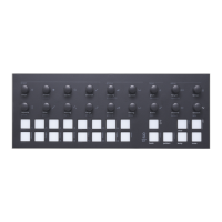
5 PIN MIDI 5 PIN to TRS MIDI
MIDI DIN 24
This is often found for MIDI
Out and Thru and enables
syncing of classic devices.
This uses 0v & 5v messages
as sync signals at 24 pulses
per quarter note (PPQN).
MIDI CC
MIDI Control Control and
Note change messages are
used to communicate
messages across MIDI with
values of 0-127. Control
Changes (CC) affect
parameter values. T-1 can
control dened CC
assignments.
SYSEX
System Exclusive. This is an
expansion of the normal MIDI
communications set up and is
typically used for transferring
data such as back ups,
patches, presets and
rmware updates to and from
devices.
MIDI
Musical Instrument Digital
Interface. A protocol for
communicating between
electronic musical gear.
Never connect MIDI gear to
incompatible DIN signals. T-1
has USB and 5 Pin MIDI
connectivity options.
MIDI STANDARDS
While there are MIDI
standards dened, many
synth developers interpret
this in slightly different ways.
Its always worth reviewing
the documentation with each
to fully understand each
device level implementation.
SDS
Sample Dump Standard. This
is an older transfer protocol
used for transferring data to
and from devices. This is
rarely seen nowadays.
MIDI DIN 48
This is often found for MIDI
Out and Thru and enables
syncing of classic devices.
This uses 0v & 5v messages
as sync signals at 48 pulses
per quarter note (PPQN).
MSB & LSB
Most Signicant Byte and
Least Signicant Byte. MSB
provides the 128 data
resolution which is ok for
most MIDI applications. More
advanced devices use MSB
and LSB values increasing
resolution to 16,384 steps.
NRPN
Non-Registered Parameter
Number is part of the MIDI
standard. CC and NRPN are
technically very similar but
NRPN is less well dened in
the standards. NRPN uses
more data and can give
better control.
The term ‘primary lead’ will refer, in this guide to a device that has the main control responsibility.
For example, one which controls the clock and transport and is the central lead. It is typical for T-1
to be a primary lead. A device which will be controlled by, and will follow the primary lead device
and which will be subservient by responding to the main control messages will be called a
‘secondary follower’. A synthesizer module could be a typical secondary follower.
 Loading...
