191
The T-1 Notebook : Reference & Guide
190
The T-1 Notebook : Reference & Guide
NOTES
Analog Connectivity
9
Analog Connectivity
9
9.1 General Trig & CV Concepts
Analog control with audio gear is typically based on a voltage signal. There
are several applications of voltage control depending on manufacturer
preference and standards. In Eurorack, the most common modular format,
a 0-5V signal is usually used for triggering events i.e. Note, On, Off and for
modulation, pitch and velocity. Other Voltage ranges of -5V to +5V bi-polar,
0-8V or 0-10V can also be found in Eurorack format.
Trigger & Gate
A trigger is a short pulse that activates an event. Typically a note is
activated by a trigger. In T-1 Triggers have a 0-5V range although most
gear will recognise the switch is triggered below the 5V threshold. Formats
may differ in whether the increase voltage from 0 to 5V triggers an event or
whether the trigger operates on a falling edge 5V to 0. These are V-Trig and
S-Trig formats respectively. A trigger differs from a gate in that it consists of
shorter pulses. A gate would normally be controlled to be held high or low
for longer periods.
T-1 triggers are 0-5V although the input voltage tolerance is up to 10V.
Control Voltage
Control Voltage or CV is used to control absolute or relative values. A
typical application is to control Pitch of an oscillator. The most common
format being 1V / Octave although Hz/Volt is an alternative. A trigger would
activate a note and the note value set by CV. Other modulation destinations
such as affecting parameters for effects and modules are also controlled by
CV. T-1 CV can also be congured as gates.
T-1 operates with a 0-5V CV range.
Clock
A clock is used to synchronise timing between devices. Pulses are
generated typically by a nominated primary lead and other secondary
devices will synchronise to this clock. The format is based on PPQN -
Pulses per Quarter Note with 24PPQN being most common. Other options
are available but the most important consideration is to match up the clock
with devices in the conguration. A reset is also available in T-1.
T-1 Clock Hierarchy - 1. Analog Clock 2. MIDI Clock 3. Link
T-1 has clock 2, 4, 8, 12, 16, 24 PPQN Options. Reset level 5V.
1
Pitch
V/Oct - 1 Volt per Octave
Note: Frequency to the perception of pitch is logarithmic
Volts
4
3
2
5
0
Velocity
Modulation
Voltage ranges may vary between devices and formats
Volts
3.75
2.5
1.25
5
A1
55Hz
0
A2
110Hz
32
A3
220Hz
64
A4
440Hz
95
A5
880Hz
127
V-Trig
0 to +5V
S-Trig
+5V to 0V
Time
Time
0
Volts
+5
0
Volts
+5
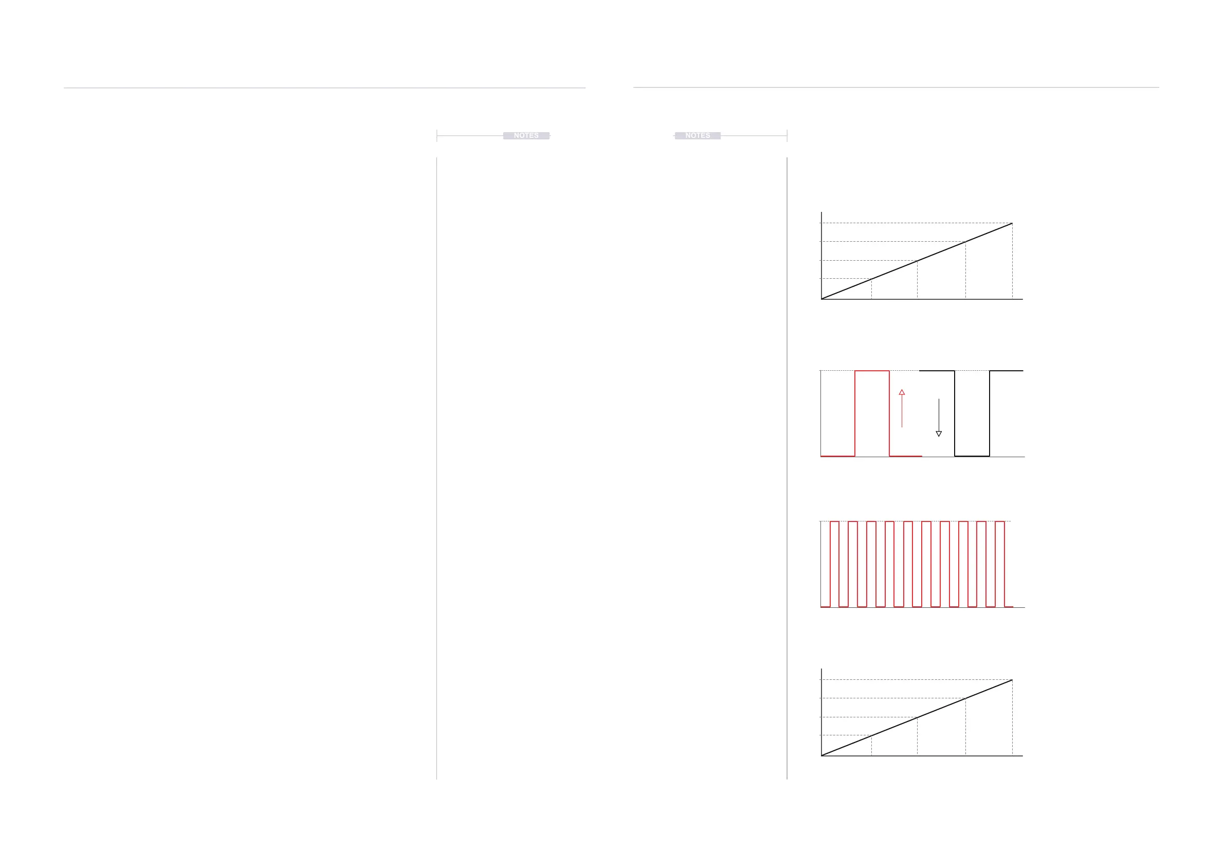
Example CV Concepts and Applications.
Diagrams and values for Illustrative purposes only. Actual behaviour will be based on specic devices.
Pitch
Volts per Octave is a common
approach to controlling pitch of an
analog device, especially in Eurorack.
Occasionally this may also follow an
alternative Hz / Volt format, used by
Korg and Yamaha.
Range
Control Voltages can also modulate
various parameters. These may be %
ranges, absolute values, offsets etc. T-
1 has a conguration option for
velocity. While this is based on the
velocity of notes it can be used to
modulate any analog parameter.
Trig
A trigger is a short voltage pulse that
activates an event. A gate is similar but
usually a longer, controlled length. A
trigger is often used for note on, off
and switch functions. V-Trig is the most
common, 0-5 rise to trigger. S-Trig
activates on a falling 5-0 voltage level.
Clock
An analog clock operates on a series
of pulses to synchronise devices.
Pulses are normally measured Pulses
per Quarter Note - PPQN. T-1 has
adjustable settings for analog clock
rates and pulse width to help match up
to devices. Analog clock is the highest
order in the clock hierarchy.
Trigger
Clock
NOTES
 Loading...