2
4400 Series UPS Seismic Kit Installation Instructions – 94016-002
15-30 kVA Seismic Adapter Kit (Cont.)
1. Prepare the oor anchorages. Arrange the anchorages to ac-
commodate the nal layout including placement of ancillary bat-
tery and/or Auxiliary cabinets. (Figure 1.2)
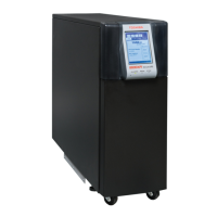
2. Prepare the wall anchorages. Key measurements o the an-
chorage placement in Step 1. (Figure 1.3)
3. Table 1 lists the components of the 30kVA Seismic Kit. Figure
1.5 show the Seismic anchorage components in the Seismic Kit
for the 30kVA cabinets.
4. Assemble the fastener groups in Table 1, [4a-4c], [10a-10c], and
[11a-11c] as shown in Figure 1.1.
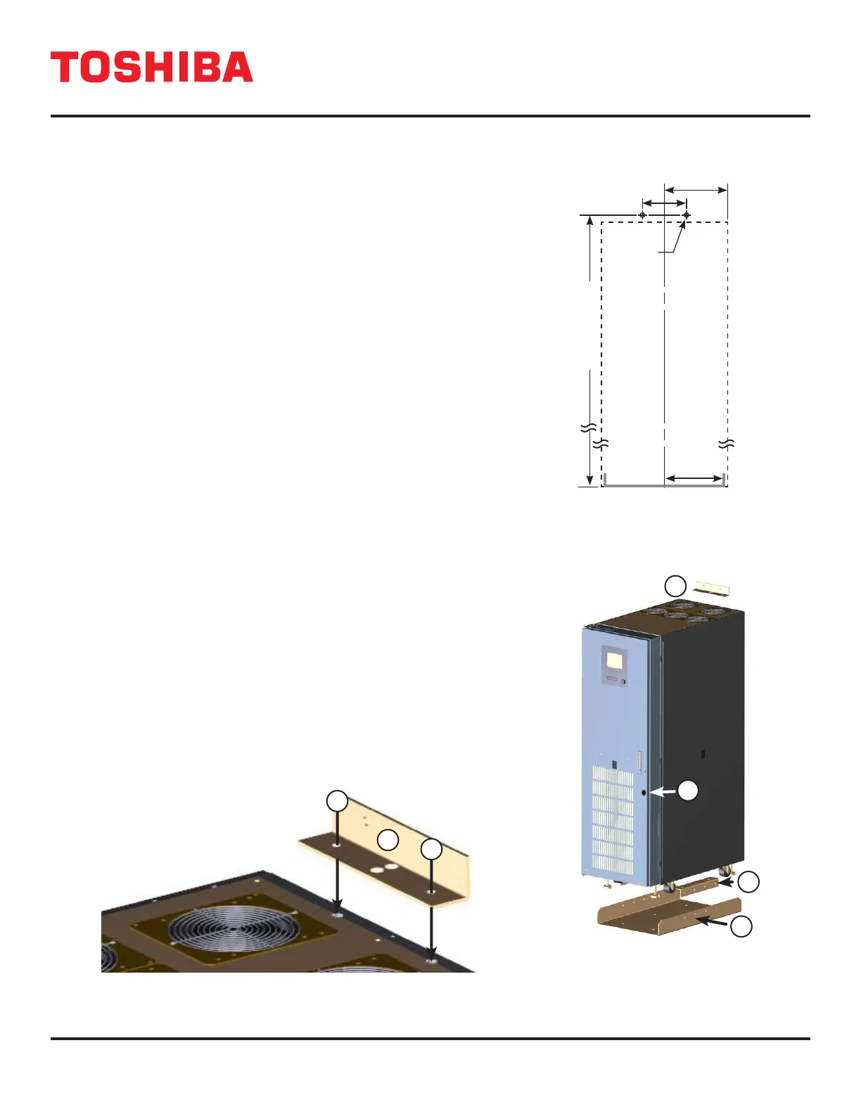
5. Secure the Top Seismic Bracket [1] to the top rear of the UPS
using two (2) fastener group [11]. (Figure 1.4)
6. Secure the Base Mounting Bracket, [3], to the oor anchors
installed in Step 1.
7. Roll the 15-30 kVA UPS cabinet between the two vertical sides of
the Base Mounting Bracket, [4]. (Figure 1.6)
8. Line up the UPS so the bolt holes on the Bottom Seismic Brack-
ets line up with the holes on the Seismic Base Plate vertical
sides.
9. Secure the UPS to the Seismic Base Plate using the remaining
eight (8) fastener group [11]. Insert the bolts through the Seismic
Bracket to the welded nuts on the Seismic Base Plate. (Figure
1.6)
10. Secure the Top Seismic Bracket, [1], to the wall anchors installed
in Step 2.
11. Once installation is complete, use the single Fastener Group [4]
to secure the door of the UPS. (Figure 1.7)
11
11
1
FIGURE 1.3: 15-30KVA SEISMIC
ANCHORAGE - WALL PATTERN
66.44 in. (1688 mm)
10.05 in
(255 mm)
5 in (127 mm)
1/4” Bolt
Anchor (2)
9.27 in
(471 mm)
Base Mounting Bracket
Cabinet Wall Footprint
P/N 440300SEISMICKIT
1
2
3
4
FIGURE 1.4: TOP SEISMIC BRACKET INSTALLATION
FIGURE 1.5: SEISMIC KIT
COMPONENTS (15-30 KVA)
 Loading...