–4–
EN
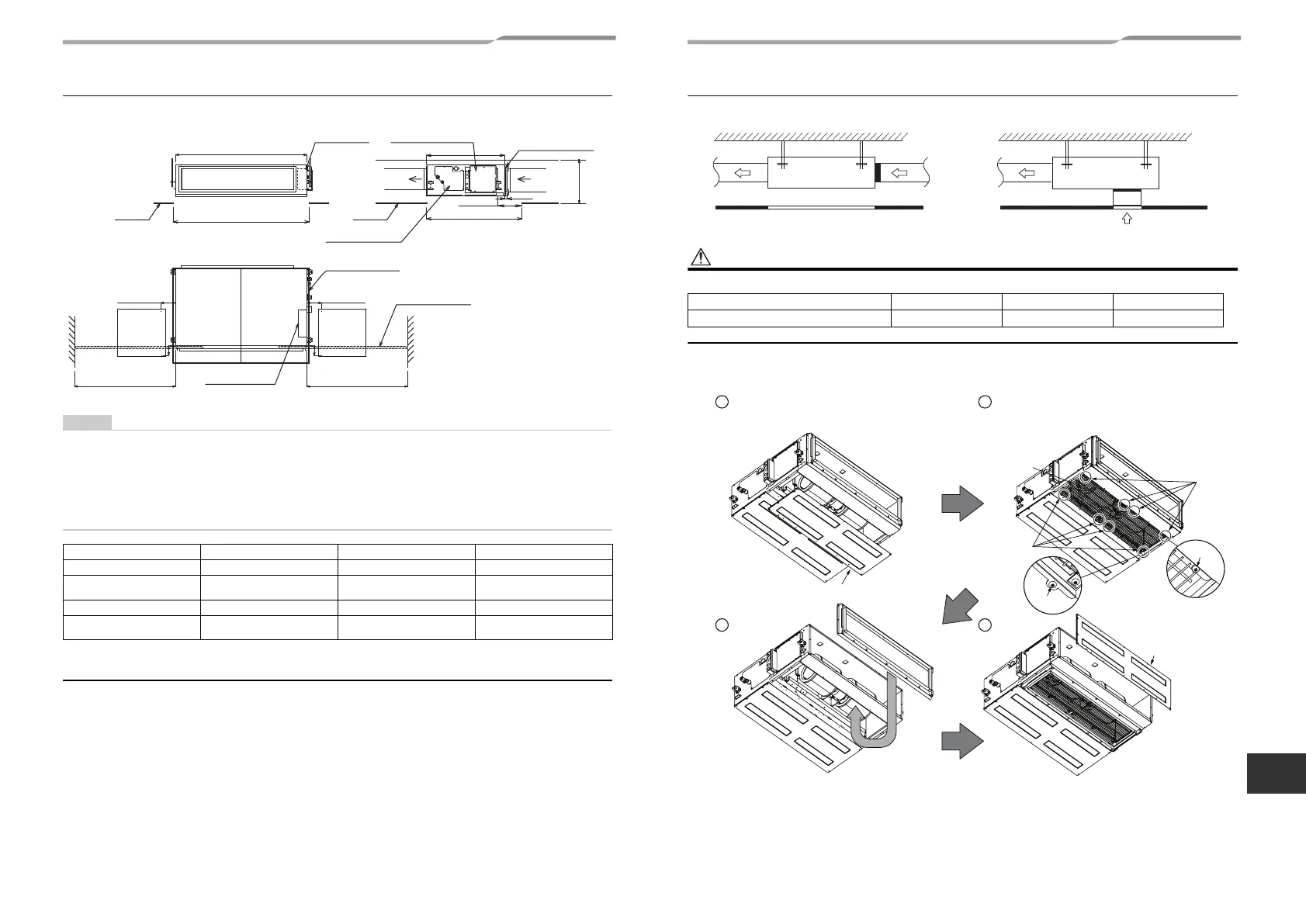
Installation space Unit: in (mm)
Reserve sufficient space required for installation or service work.
• Set check port A for maintaining the electrical control box, filter, drain pump, drain pipe, and refrigerant pipe.
• Replace the filter through check port A or B.
(If you pull out the filter in the opposite direction of the electrical control box, check port B is required.)
Reserve space D required for attaching or detaching the filter.
Otherwise, the filter cannot be replaced.
• When pulling the refrigerant pipe, drain pipe, etc., avoid the filter port. Otherwise, the filter cannot be replaced.
• The indoor unit is not equipped with an air filter. Procure and install one locally.
• Set a ceiling opening port for maintaining the fan, fan motor, etc. Otherwise, they cannot be maintained.
Filter cleaning sign term setting
The lighting term setup of the filter sign (Notification of filter cleaning) of the remote control can be changed
according to the condition of installation.
For setup method, refer to “Filter sign setting” in the Applicable controls of this Manual.
MODEL MMD- AP007 to AP012 AP015 to AP018 AP021 to AP048
Unit width 27.6” (700) 39.4” (1000) 53.2” (1350)
Air filter width 25.0” (635)
38” (18”+20”)
(965 (457+508))
52” (20”+20”+12”)
(1321 (508+508+305)
Ceiling opening size C 29.5” (750) 41.3” (1050) 55.1” (1400)
Space required for attaching or
detaching the filter D
28.7” (730) 23.6” (600) 40.5” (1030)
Electrical control box
Air filter
(locally procured)
5.9” (150)
Ceiling opening size
15.5” (400)
(Min.) *1
Air discharge
Ceiling opening size C
Electrical
control box
Check port A
17.7” × 17.7”
(450 × 450)
Air discharge
5.9” (150) or more
Air intake
1.2” (30)
Ceiling
Ceiling
Unit width
31.5” (800)
Ceiling opening size
38.6” (980)
Drain pan / Drain
pump check cover
Space required for attaching or
detaching the filter D
Check port B
17.7” × 17.7”
(450 × 450)
Air filter
(locally procured)
Space required for attaching or
detaching the filter D
5.9” (150) or more
4” (100)
Electrical control
box
4” (100)
*1:
For air intake from
underneath, reserve a
space of 17.7” (450 mm)
or more.
Arranging the under intake type
For air intake from under air intake, be sure to attach the FAN-GUARD. (Sold separately)
For air intake from under air intake, replace the cover (A) and filter flange as shown below before installing
the unit.
<Back air intake> <Under air intake>
Model MMD- AP007 to AP012 AP015 to AP018 AP021 to AP048
FAN-GUARD
model name TCB-IG071BUL-1 TCB-IG151BUL TCB-IG211BUL
Screw
Screw
Screw
Screw
Remove the cover plate A.
Fix the cover plate A.
Fan guard
Attach the FAN-GUARD. (Sold separately)
Use the supplied screws.
Remove the filter
flange and then fix it to
the bottom surface.
7-EN 8-EN
+00EB99808801_01EN.book Page 4 Monday, April 11, 2016 2:30 PM
 Loading...