Do you have a question about the Toshiba Carrier MMK-AP0123H2UL and is the answer not in the manual?
| Brand | Toshiba |
|---|---|
| Model | Carrier MMK-AP0123H2UL |
| Category | Air Conditioner |
| Language | English |
Explains safety indications, illustrated marks, and warning labels found in the manual.
Covers essential safety practices for handling refrigerant, tools, parts, and electrical components.
Details safety procedures for insulator checks, ventilation, electrical shock prevention, and post-repair checks.
Discusses safety precautions and handling guidelines for the new R410A refrigerant.
Lists the specific tools and materials necessary for working with R410A refrigerant.
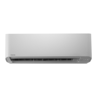
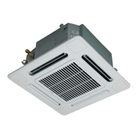
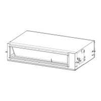
Provides detailed technical specifications for various indoor unit types like Cassette, Ceiling, and High Wall.
Presents detailed diagrams and dimensions for different indoor unit models.
Illustrates the internal wiring connections for different indoor unit types.
Details the specifications and ratings for various internal components of indoor units.
Shows the overall refrigerating cycle and outlines the functions of key components.
Explains the operational control logic and modes for cassette and ceiling indoor units.
Details the control logic and operational modes specific to high wall indoor units.
Covers capacity control, air speed, freeze prevention, recovery, filter sign, Hi POWER, SLEEP, PRESET, etc.
Illustrates how indoor units connect and communicate with controllers and outdoor units.
Identifies key components and connectors on the indoor unit's main P.C. boards (MCC-1570, MCC-1402).
Describes optional connectors, switches, and DIP settings for P.C. boards.
Provides step-by-step instructions for conducting test runs using remote controllers.
Explains how to check unit operation and clear error codes remotely.
Details the procedure for setting various indoor unit functions using DN codes.
Covers remote ON/OFF control, ventilation fan control, and other advanced functions.
Guides users on setting and confirming indoor unit addresses for system configuration.
Outlines common issues, potential causes, and the general troubleshooting process.
Lists and explains error codes detected by indoor units and their typical causes.
Lists and explains error codes detected by outdoor units and their typical causes.
Details error codes specific to the TCC-LINK central control system.
Provides graphs showing the resistance characteristics of indoor unit temperature sensors.
Step-by-step instructions for removing and installing various indoor unit parts.
Details the process for replacing the indoor P.C. board and configuring settings.
Provides detailed exploded diagrams and part numbers for various indoor unit models.
Outlines requirements and safety measures related to refrigerant concentration limits in rooms.