Do you have a question about the Toshiba Carrier MMU-AP0182H2UL and is the answer not in the manual?
| Cooling Capacity | 5.0 kW |
|---|---|
| Heating Capacity | 5.6 kW |
| Power Supply | 220-240V, 50Hz |
| Outdoor Unit Noise Level | 49 dB |
| Outdoor Unit Dimensions (WxHxD) | 780 x 540 x 285 mm |
Defines danger, warning, and caution indications used in the manual.
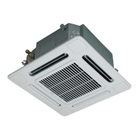
Detailed technical specifications for 4-way cassette indoor units.
Detailed technical specifications for compact 4-way cassette indoor units.
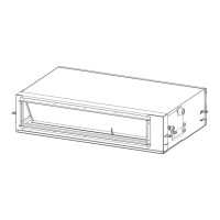
Detailed technical specifications for ceiling type indoor units.
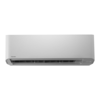
Detailed technical specifications for high wall type indoor units.
Exploded views showing external dimensions of 4-way cassette units.
Exploded views showing external dimensions of compact 4-way cassette units.
Exploded views showing external dimensions of ceiling type units.
Exploded views showing external dimensions of high wall type units.
Wiring diagrams for 4-way cassette indoor units.
Wiring diagrams for compact 4-way cassette indoor units.
Wiring diagrams for ceiling type indoor units.
Wiring diagrams for high wall type indoor units.
Ratings and specifications for parts used in 4-way cassette units.
Ratings and specifications for parts used in compact 4-way cassette units.
Ratings and specifications for parts used in ceiling type units.
Ratings and specifications for parts used in high wall type units.
Explains control functions for 4-way cassette, compact cassette, and ceiling types.
Explains control functions specific to high wall type indoor units.
Block diagram of indoor controller with wired remote connection.
Block diagram of indoor controller with wireless remote connection.
Block diagram for indoor controller with both wired and wireless remotes.
Details of the MCC-1570 P.C. board used in 4-way cassette units.
Details of the MCC-1402 P.C. board for compact cassette and ceiling units.
Step-by-step guide for performing cooling and heating test runs.
Methods for clearing errors from the remote controller and indoor unit.
General troubleshooting information, applicable models, and required tools.
Systematic steps for diagnosing faults using check codes.
List and explanation of error codes detected by outdoor units.
Specific error codes related to IPDU faults in outdoor units.
Using remote controller display information for troubleshooting.
List of check codes displayed on remote/outdoor units and locations to check.
Steps for replacing the main P.C. board and establishing unit correspondence.
Steps to write setting data, including addresses, into the EEPROM.
Steps for replacing the service P.C. board for high wall units.
Steps to write setup contents into EEPROM for high wall units.