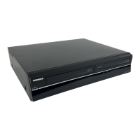
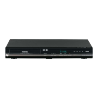
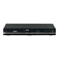
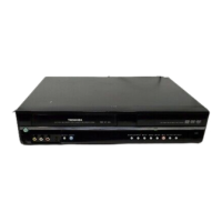
This document is a service manual for the Toshiba DVR19DTKB2 DVD/Video Cassette Recorder, published in September 2009. It provides comprehensive information for servicing, maintenance, and repair, emphasizing green product procurement and lead-free solder usage.
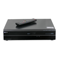
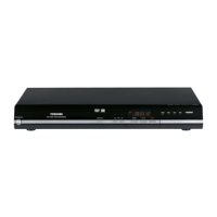
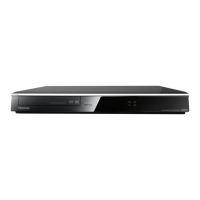
The DVR19DTKB2 is a versatile home entertainment device combining the functionalities of a DVD recorder and a VCR. This dual-format capability allows users to record and play back content on both DVD and VHS formats, offering flexibility for managing various media types. The device supports recording to DVD-RW (VR format), DVD-R (video format), DVD+RW, and DVD+R discs. For VCR operations, it features a four-head system, ensuring good quality video playback and recording.
Technical Specifications:
- VCR Video Heads: Four heads
- Power Requirements: 220-240 V ~ 10 %, 50 Hz ± 0.5 %
- Power Consumption (operating): 25 W
- Power Consumption (standby): 0.95 W
- Weight: 4.9 kg
- Dimensions (width x height x depth): 435 x 79.5 x 388 mm
- Operating Temperature: 5 °C to 40 °C
- Operating Humidity: Less than 80 % (no condensation)
- TV System: PAL-I
- Recording Format (DVD): Video Recording (VR) format (DVD-RW only), video format (DVD-RW, DVD-R), +VR format (DVD+RW, DVD+R)
- Recordable Discs: DVD-ReWritable, DVD-Recordable, DVD+ReWritable, DVD+Recordable
- Video Recording Format (Sampling Frequency): 13.5 MHz
- Video Recording Format (Compression Format): MPEG
- Audio Recording Format (Sampling Frequency): 48 kHz
- Audio Recording Format (Compression Format): Dolby Digital
- Tuners:
- Analogue Channels: IRA - E69 (For analogue channels)
- DVB-T Channels: E21 - E69 (For DVB-T channels)
- Input/Output (Front Panel):
- DV Input: IEEE 1394
- USB Input: USB 2.0
- Input/Output (Rear Panel):
- VHF/UHF Antenna Input/Output: VHF/UHF set 75 Ω
- Audio Input/Output: Two 2-pin scart sockets (AV1, AV2)
- Video Input/Output: Two 21-pin scart sockets (AV1, AV2), Two 1-pin S-Video
- Component Video Output: Three RCA connectors (Y: 1.0 Vp-p (75 Ω), PR/CR: 0.7 Vp-p (75 Ω) each, PB/CB: 0.7 Vp-p (75 Ω) each)
- Audio Output Level: 2 Vrms (output impedance: 680 Ω)
- Digital Audio Output: One Coaxial pin jack (0.5 Vp-p (75 Ω))
- HDMI Output: HDMI jack
Usage Features:
- Initialization: The manual details a procedure to restore the DVD recorder and VCR to factory-default settings. This involves specific button presses on the remote control unit ([DVD], [INSTANT SKIP], [1], [2], [3]) to enter a "Version display mode," followed by pressing [ENTER/OK] to initiate the initialization process. This resets settings like "Current Clock," "Setup Changing Item," "Channel Setup," and "Timer Program."
- Firmware Renewal: A dedicated mode for updating the device's firmware is described. This involves inserting a disc with the new firmware and navigating through a menu using the remote control. The process includes steps for loading the file, updating, and then cycling the power.
- Manual Eject: Instructions are provided for manually ejecting a disc in case of a malfunction. This involves disassembling parts of the cabinet and mechanism to manually rotate a gear, allowing the disc tray to descend and the disc to be removed.
- Remote Control: A comprehensive list of remote control key codes is provided, detailing the function and corresponding code for each button, such as OPEN/CLOSE, INPUT SELECT, HDMI, ON/STANDBY, numerical keys, program up/down, timer program, setup, clear, info, text, VCR, DVD, guide, menu navigation (cursor up/down/left/right, enter/OK), display, return/back, color buttons (red, green, yellow, blue/search), playback controls (rev, play, fwd, skip down/up, stop, pause), instant skip, sat.link, time slip, dubbing, rec mode, rec, subtitle, AD, and timer set.
Maintenance Features:
- Safety Precautions: The manual emphasizes critical safety precautions, particularly regarding laser beam safety for the DVD pickup and electrical safety during servicing. It warns against direct exposure to the laser beam and highlights the importance of using specified replacement parts and insulating materials. Parts critical for safety are marked with a "!" symbol in schematics and parts lists.
- Green Product Procurement: Toshiba promotes "Green Procurement" by using lead-free solder and environmentally responsible parts. Service personnel are instructed to use lead-free solder and specified green parts for repairs to maintain compliance with WEEE & RoHS Directives.
- Lead-Free Solder Usage: A specific warning is issued against using lead-based solder for repairs, as the product is manufactured with lead-free solder. The melting temperature of lead-free solder is higher, requiring careful soldering techniques to avoid damaging components.
- Standard Notes for Servicing: Guidelines for circuit board indications (e.g., pin 1 identification for ICs and connectors) and instructions for handling FFC (Flexible Foil Connector) cables are provided.
- Flat Pack-IC Removal/Installation: Detailed procedures for removing and installing flat pack-ICs using hot-air desoldering machines or soldering irons are included, with cautions about heat exposure to surrounding components and the use of masking tape.
- Semiconductor Handling: Instructions for preventing electrostatic breakdown when handling semiconductors are given, including wearing a grounding band and using a grounded conductive sheet on the workbench.
- Service Mode Entry: For VCR servicing, a "Service Mode" can be entered by inserting a tape and connecting JP278(S-INH) to GND, which deactivates optical sensors for tape start/end and reel sensors.
- Cabinet Disassembly: A comprehensive flowchart and detailed instructions with figures guide technicians through the disassembly of the cabinet to access various internal components, including the DVD mechanism, main board, fan, power supply, VCR chassis, and DTV module. Specific notes on fragile locking tabs and the importance of replacing the DVD mechanism and main board as a unit are highlighted.
- Electrical Adjustment Instructions: Procedures for electrical adjustments, such as Head Switching Position Adjustment, are outlined. This requires an oscilloscope and an alignment tape (FL6A) to ensure proper video output waveform and prevent noise or vertical jitter.
- Troubleshooting Flowcharts: Extensive flowcharts are provided for troubleshooting various issues, categorized by power supply, DVD section, and VCR section. These charts guide technicians through a series of checks (e.g., fuse status, voltage levels, pulse signals, load circuit short-circuiting) and recommend appropriate actions (e.g., replacing specific boards or components).
- Function Indicator Symbols: A list of error messages and corresponding solutions for both VCR and DVD sections is provided. For VCR, error codes like "A R" (reel or capstan mechanism not functioning), "A T" (tape loading mechanism not functioning), "A C" (cassette loading mechanism not functioning), "A D" (drum not working properly), and "A P" (P-ON power safety detection) are explained. For DVD, error numbers and descriptions cover issues like disc reading/writing, format errors, copy protection, and timer recording failures.
- Block Diagrams: Detailed block diagrams illustrate the interconnections and signal flow within the Servo/System Control, Sub System Control, Digital Signal Process, Video Selector, Audio, Hi-Fi Audio, Power Supply, and DTV Module sections.
- Schematic Diagrams/Board and Test Points: Comprehensive schematic diagrams for the AV, Power Supply, Function/Switch/USB, Rear Jack, DVD Main, and DTV Module boards are included, along with notes on resistance/capacitance values and voltage indications for PLAY and REC modes. Test points are clearly marked.
- Waveforms: Examples of expected waveforms at various test points (e.g., V-OUT E-E, VIDEO-C, AUDIO(L)-OUT, SPDIF, VIDEO-Cb, VIDEO-Cr, VIDEO-Y, V-OUT/RF-SW, C-PB/RF-SW) are provided to aid in electrical adjustments and troubleshooting.
- Wiring Diagram: A complete wiring diagram shows the connections between different boards and components within the device.
- System Control Timing Charts: Flowcharts and timing diagrams illustrate the system control logic for tray open/close and push close operations, including voltage and event timer parameters.
- IC Pin Function Descriptions: Detailed descriptions of the functions of each pin for key ICs, such as IC501 (Microcontroller 8bit Servo/System Control) and IC612 (VFD Driver), are provided.
- Lead Identifications: Diagrams illustrating the lead configurations for various transistors, diodes, and ICs are included to assist in component identification.
- Exploded Views: Exploded views of the cabinet and deck mechanism provide a visual guide for disassembly and reassembly, with parts labeled for easy identification and cross-referencing with the mechanical parts list.
- Mechanical Parts List: A list of mechanical parts with TSB P/N, reference numbers, and descriptions is provided, including safety-critical parts marked with an exclamation mark.
- Electrical Parts List: A list of electrical parts with TSB P/N, reference numbers, and descriptions is provided, also highlighting safety-critical components.
- Deck Mechanism Section: This section focuses specifically on the VCR mechanism, including standard maintenance procedures (cleaning and replacement schedules for components like cylinder assembly, loading motor, capstan motor, belts, and heads), service fixture and tools required for adjustments, mechanical alignment procedures (tape interchangeability, X value alignment, envelope waveform adjustment, azimuth alignment), and detailed disassembly/assembly procedures for the deck mechanism with figures and notes.