2-3-3 N25E1FLMA
1-A. Preliminary/Final Checking and
Alignment of Tape Path
Purpose:
To make sure that the tape path is well stabilized.
Symptom of Misalignment:
If the tape path is unstable, the tape will be damaged.
Note: Do not use an Alignment Tape for this proce-
dure. If the unit is not correctly aligned, the tape may
be damaged.
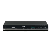
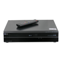
1. Playback a blank cassette tape and check to see
that the tape runs without creasing at Guide Rollers
[2] and [3], and at points A and B on the lead sur-
face. (Refer to Fig. M3 and M4.)
2. If creasing is apparent, align the height of the guide
rollers by turning the top of Guide Rollers [2] and
[3] with a Guide Roller Adj. Screwdriver. (Refer to
Fig. M3 and M5.)
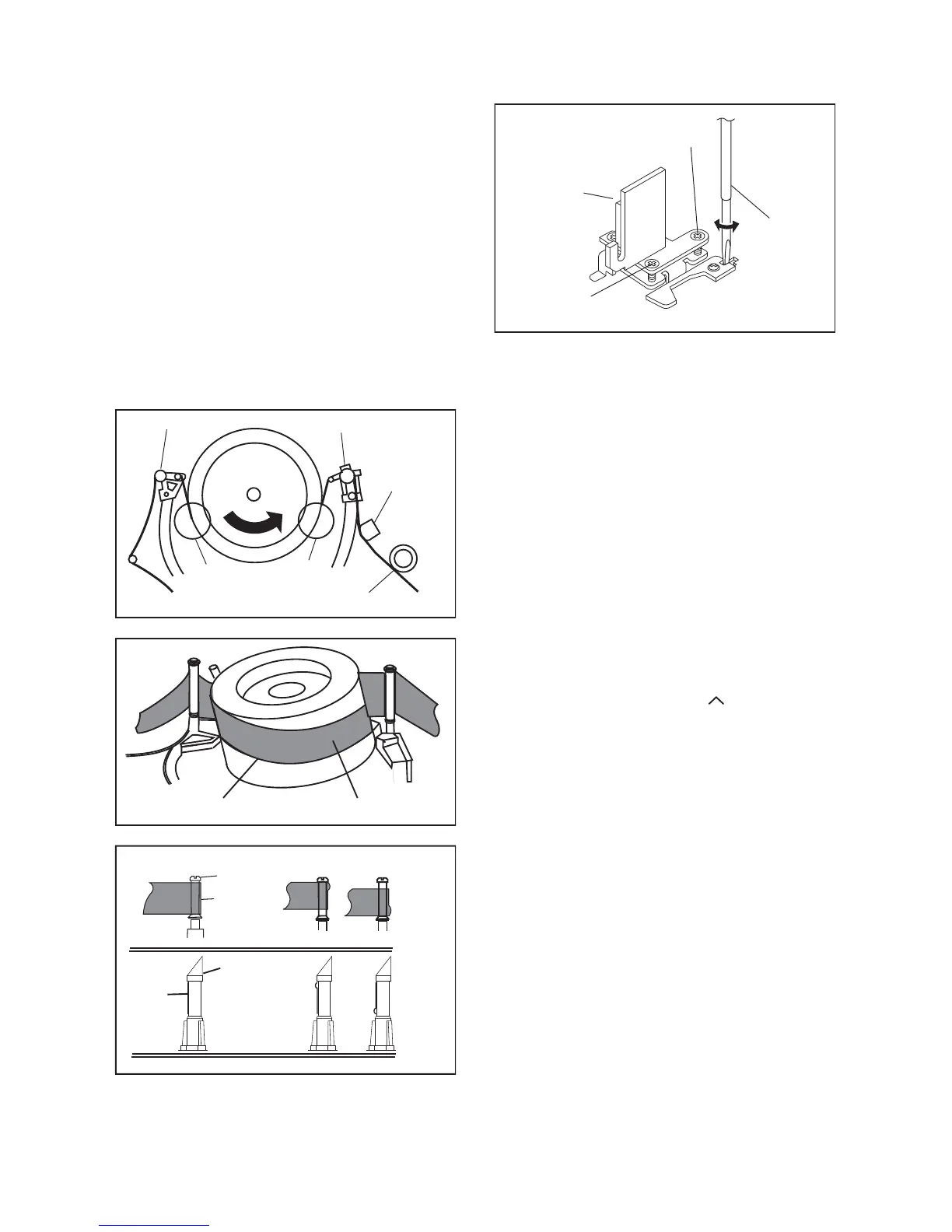
3. Check to see that the tape runs without creasing at
Take-up Guide Post [4] or without snaking between
Guide Roller [3] and ACE Head. (Fig. M3 and M5)
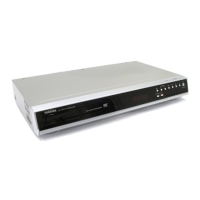
4. If creasing or snaking is apparent, adjust the Tilt
Adj. Screw of the ACE Head. (Fig. M6)
1-B. X Value Alignment
Purpose:
To obtain maximum PB FM envelope signal at the pre-
set position of the Tracking Control Circuit, align the
Horizontal Position of the ACE Head.
Symptom of Misalignment:
If the Horizontal Position of the ACE Head is not prop-
erly aligned, maximum PB FM envelope cannot be
obtained at the preset position of the Tracking Control
Circuit.
1. Connect the oscilloscope to TP301 (C-PB) and
TP503 (CTL) on the BOARD AV. Use TP504 (RF-
SW) as a trigger.
2. Playback the Gray Scale of the Alignment Tape
(FL6NS8) and confirm that the PB FM signal is
present.
3. Set the Tracking Control Circuit to the preset posi-
tion by pressing [PROGRAM ] button and then
[ B] (VCR) button on the unit. (Refer to note on
bottom of page 2-3-4.)
4. Use the Flat Screwdriver so that the PB FM signal
at TP301 (C-PB) is maximum. (Fig. M6)
Guide Roller [2]
Guide Roller [3]
A
B
Take-up Guide Post [4]
ACE Head
Fig. M3
Lead Surface of Cylinder
Tape
Fig. M4
Take-up Guide
Post [4]
Tape
Guide Roller
Tape
Correct
Incorrect
Fig. M5
Azimuth Adj. Screw
Flat
Screwdriver
Tilt Adj. Screw
ACE Head
Fig. M6
 Loading...