2-4-4 N25E1AVDA
[1]
(S-1)
(S-1)
Fig. DM3H
[2]
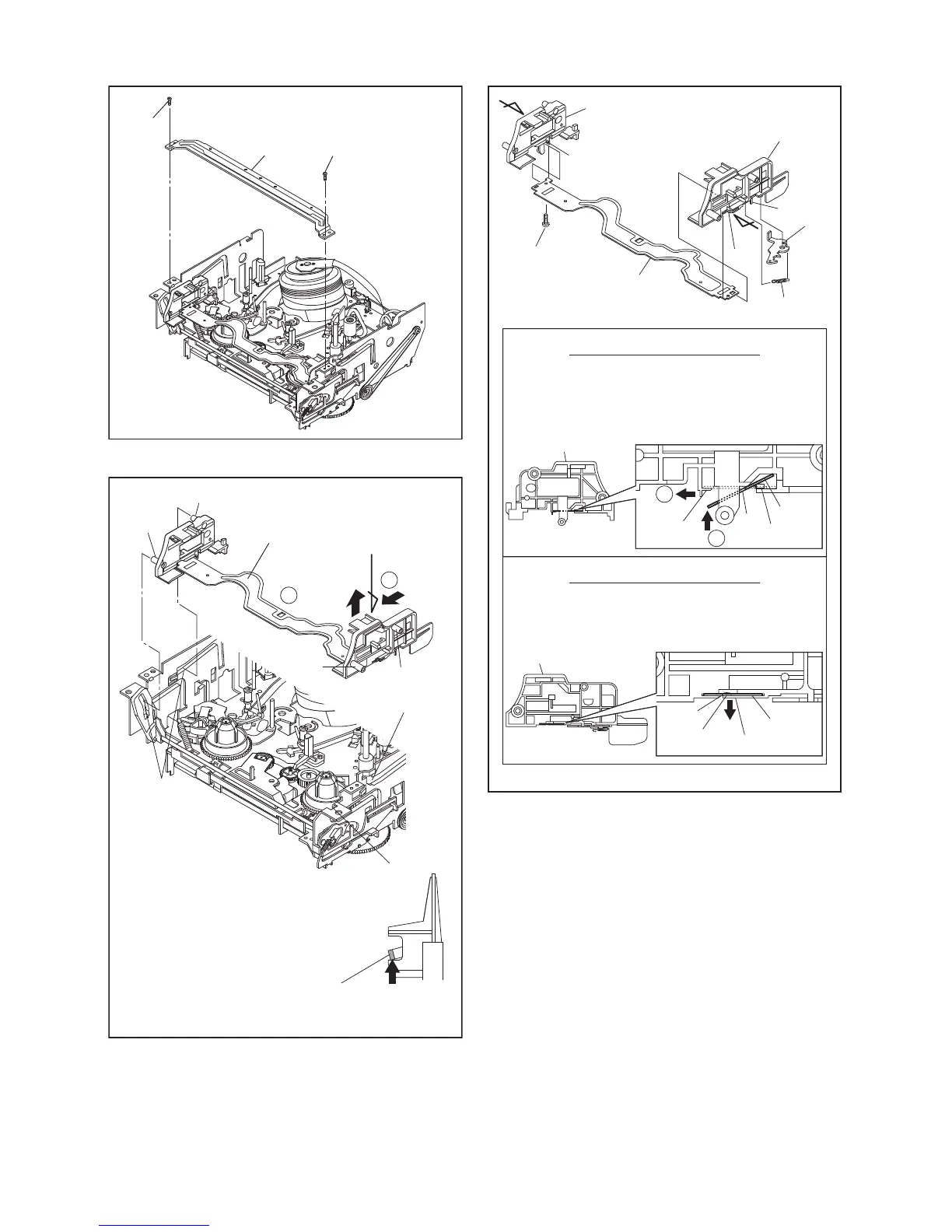
Locking tab
View for A
First, while pushing the locking tab as
shown in the right, slide and pull up the right
side on [2] to release Pin A and Pin B from
the slots A.
Then, remove Pin C and Pin D on [2] from
the slots B as shown.
Pin A
Slots B
Pin C
Pin B
Pin D
Slot A
Slot A
Fig. DM4H
Pull up
Slide
1
2
A
[3]
[6]
[6]
(L-2)
Pin A
Hole A
Pin B
Hole B
(L-1)
First, insert [6] diagonally in [3] as shown below. Then,
install [6] in [3] while pushing (L-1) in the direction of
the arrow. After installing [6] in [3], confirm that pin A
of [3] enters hole A of [6] properly.
Installation of [3] and [6]
View for A
2
1
[4]
Install [6] in [4] while pulling (L-2) in the direction of
the arrow. After installing [6] in [4], confirm that pin B
of [4] enters hole B of [6] properly.
Installation of [4] and [6]
View for B
[3]
[4]
[5]
[6]
(L-1)
(L-2)
(P-1)
(L-3)
(S-1A)
A
B
Fig. DM5H
 Loading...