1-6-2 E9TK0DC
Note:
(1): Identification (location) No. of parts in the figures
(2): Name of the part
(3): Figure Number for reference
(4): Identification of parts to be removed, unhooked,
unlocked, released, unplugged, unclamped, or
desoldered.
P=Spring, L=Locking Tab, S=Screw,
CN=Connector
*=Unhook, Unlock, Release, Unplug, or Desolder
e.g. 6(S-1) = six Screws (S-1),
5(L-1) = five Locking Tabs (L-1)
(5): Refer to “Reference Notes.”
Reference Notes
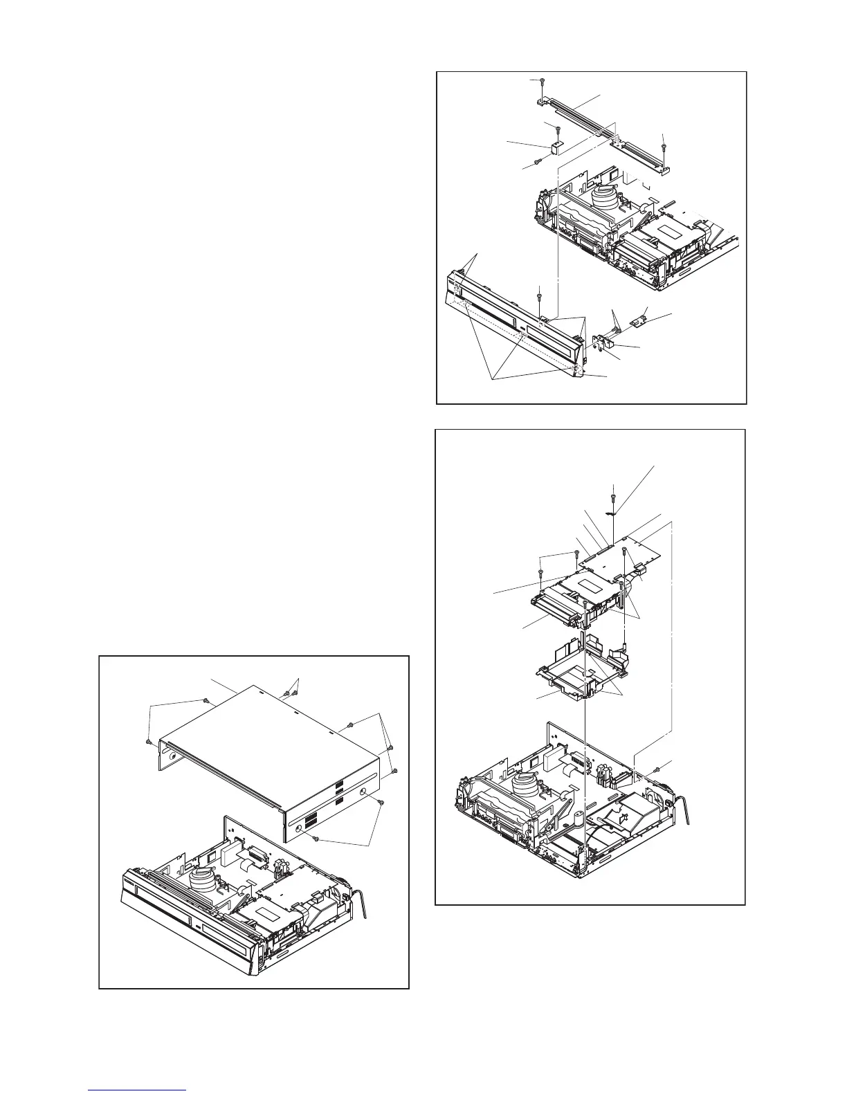
1. Locking Tabs (L-1) and (L-2) are fragile. Be careful
not to break them.
1-1. Remove Screw (S-2).
1-2. Release four Locking Tabs (L-1).
1-3. Release three Locking Tabs (L-2).
1-4. Disconnect Connector (CN6001), and
remove the Front Assembly.
2. The DVD Mechanism & DVD MAIN BOARD
Assembly is adjusted as a unit at factory.
Therefore, do not disassemble it. Replace the
DVD Mechanism & DVD MAIN BOARD
Assembly as a unit.
3. When reassembling, solder wire jumpers as
shown in Fig. D7.
4. Before installing the Deck Assembly, be sure to
place the pin of LD-SW on the BOARD AV as
shown in Fig. D7. Then, install the Deck Assembly
while aligning the hole of Cam Gear with the pin of
LD-SW, the shaft of Cam Gear with the hole of LD-
SW as shown in Fig. D7.
(S-1)
(S-1)
(S-1)
(S-1)
[1] Cover Top
Fig. D1
(L-1)
(L-2)
(L-1)
(S-5)
(S-4)
(S-2)
Front
Support
USB Holder
CN6001
USB Plate Earth
[2] Front Assembly
[3] BOARD
USB
[4] Front Bracket
(S-4)
(S-4)
(S-3)
Fig. D2
(S-9)
CN101
CN901
CN701
CN981
Mecha Plate
Earth
CN502-D
(S-7)
(S-6)
* See Reference Notes 2.
Dust
Cover
Hook
[5] *DVD
Mechanism
& DVD MAIN
BOARD
Assembly
(S-7)
(S-8)
Fig. D3
 Loading...