1-11-3 E9TK3TR
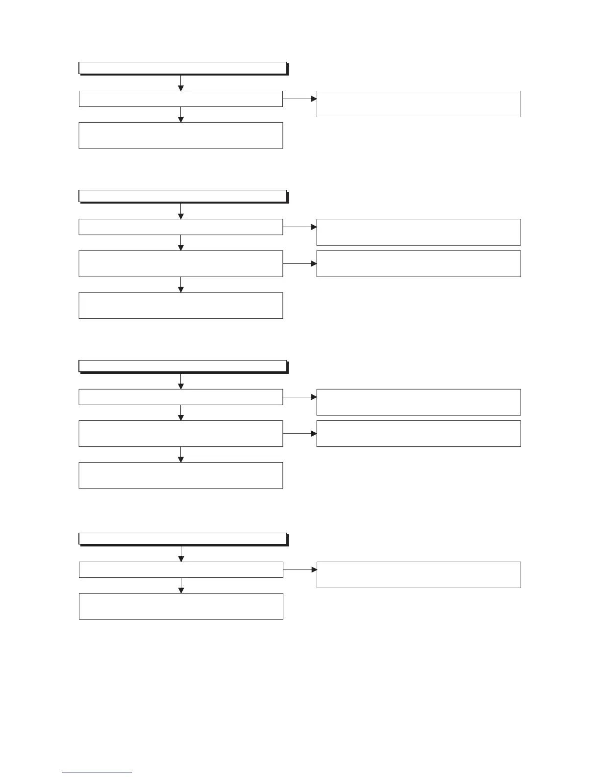
FLOW CHART NO.11
AL+5V is not outputted.
Is the supply voltage 5V fed to the cathode of D016? Check D016, D1102 and their periphery, and replace
P4(PW/SW ASSEMBLY) if defective.
No
Ye s
Check for load circuit short-circuiting or leak, and
replace P1(AV ASSEMBLY) if defective.
FLOW CHART NO.12
P-ON+5V(VCR) is not outputted.
Is 5V voltage supplied to collector of Q1517? Refer to "FLOW CHART NO.11"<AL+5V is not
outputted>.
No
Ye s
Is the "H" pulse (approximately 6V) inputted to
the base of Q1517?
Refer to "FLOW CHART NO.9"<P-ON+9V(VCR) is
not outputted>.
No
Ye s
Check Q1517 and their periphery, and replace
P1(AV ASSEMBLY) if defective.
FLOW CHART NO.13
ECO+5V is not outputted.
Is 5V voltage supplied to collector of Q1520? Refer to "FLOW CHART NO.11"<AL+5V is not
outputted>.
No
Ye s
Is the "H" pulse (approximately 6V) inputted to
the base of Q1520?
Refer to "FLOW CHART NO.14"<ECO+9V is not
outputted>.
No
Ye s
Check Q1520 and their periphery, and replace
P1(AV ASSEMBLY) if defective.
FLOW CHART NO.14
ECO+9V is not outputted.
Is 12V voltage supplied to collector of Q1521?
Refer to "FLOW CHART NO.8"<AL+12V(ECO+12V)
is not outputted>.
No
Ye s
Check Q1521 and their periphery, and replace
P1(AV ASSEMBLY) if defective.
 Loading...