1-11-15 E9TK3TR
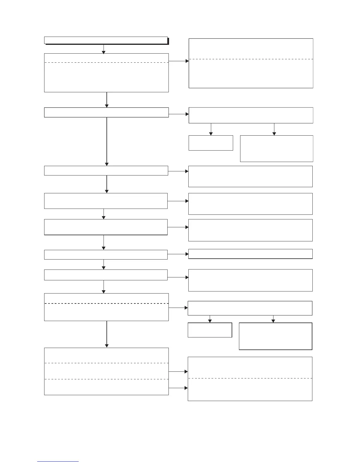
FLOW CHART NO.11
Hi-Fi E-E audio does not operate normally.
No
No
Are the audio signals inputted to each pin of IC1509?
Check the line between audio input terminal and each
pin of IC1509, and replace P1(AV ASSEMBLY), P6
(BOARD DTV MODUDLE UNIT) or TU1800 if defective.
Are the audio signals outputted to Pin(69,70) of IC1509?
Ye s
Ye s
IC1509 AUDIO-IN1 (AV1)84,85PIN
IC1509 AUDIO-IN2 (AV2)89,90PIN
IC1509 TUNER-AUDIO86,87PIN
IC1509 DTV-AUDIO93,94PIN
IC1509
→
JK150484,85PIN
AUDIO-IN1 (AV1)
IC1509
→
JK200189,90PIN
IC1509
→
TU1800 6PIN86,87PIN
TUNER-AUDIO
IC1509
→
CN1800 29,30PIN 93,99PIN
DTV-AUDIO
AUDIO-IN2 (AV2)
Check the ECO+5V, ECO+9V
line and replace P1(AV
ASSEMBLY) or P4(PW/SW
ASSEMBLY)if defective.
Replace P1(AV
ASSEMBLY).
Ye s N o
Is 5V voltage supplied to Pin(27,29,47,63) of IC1509?
Is 9V voltage supplied to Pin(75) of IC1509?
Ye s
Check the line between Pin(73,74) of IC1509 and audio
terminal (JK1504), and replace P1(AV ASSEMBLY) if
defective.
Are the audio signals outputted to the specific output
terminal?
Are the audio signals outputted to the audio terminal
(JK1504)?
Are the audio signals outputted to the audio terminal
(JK2001)?
Ye s
IC1509 73,74PIN AUDIO-OUT 1 (AV1)
IC1509 71,72PIN AUDIO-OUT 2 (AV2)
Are the audio signals outputted to each pin of IC1509?
No
No
Check the line between Pin(71,72) of IC1509 and audio
terminal (JK2001), and replace P1(AV ASSEMBLY) if
defective.
No
Check the ECO+5V, ECO+9V
line and replace P1(AV
ASSEMBLY) or P4(PW/SW
ASSEMBLY)if defective.
Replace P1(AV
ASSEMBLY).
Ye s N o
Is 5V voltage supplied to Pin(27,29,47,63) of IC1509?
Is 9V voltage supplied to Pin(75) of IC1509?
Check the line between Pin(69,70) of IC1509 and
Pin(4,50) of IC451, and replace P1(AV ASSEMBLY)
if defective.
Check the circuit of P-ON+5V and P-ON+9V, and
replace P1(AV ASSEMBLY) or P4(PW/SW ASSEMBLY)
if defective.
Is the 5V voltage supplied to Pin(16,32,35,36,46,55) of
I
C451, and the 9V voltage supplied to Pin(69) of IC451?
Is the serial data and the clock signal supplied to
Pin(37,38) of IC451?
Is the audio signal outputted to Pin(74,76) of IC451?
Is the audio signal inputted into Pin(81,82) of IC1509?
Is the audio signal inputted to Pin(4,50) of IC451?
Ye s
Ye s
Ye s
Ye s
No
No
No
No
No
Check the line between Pin(37,38) of IC451 and
Pin(71,72) of IC501, and replace P1(AV ASSEMBLY)
if defective.
Check the line between Pin(74,76) of IC451 and
Pin(81,82) of IC1509, and replace P1(AV ASSEMBLY)
if defective.
Replace P1(AV ASSEMBLY).
 Loading...