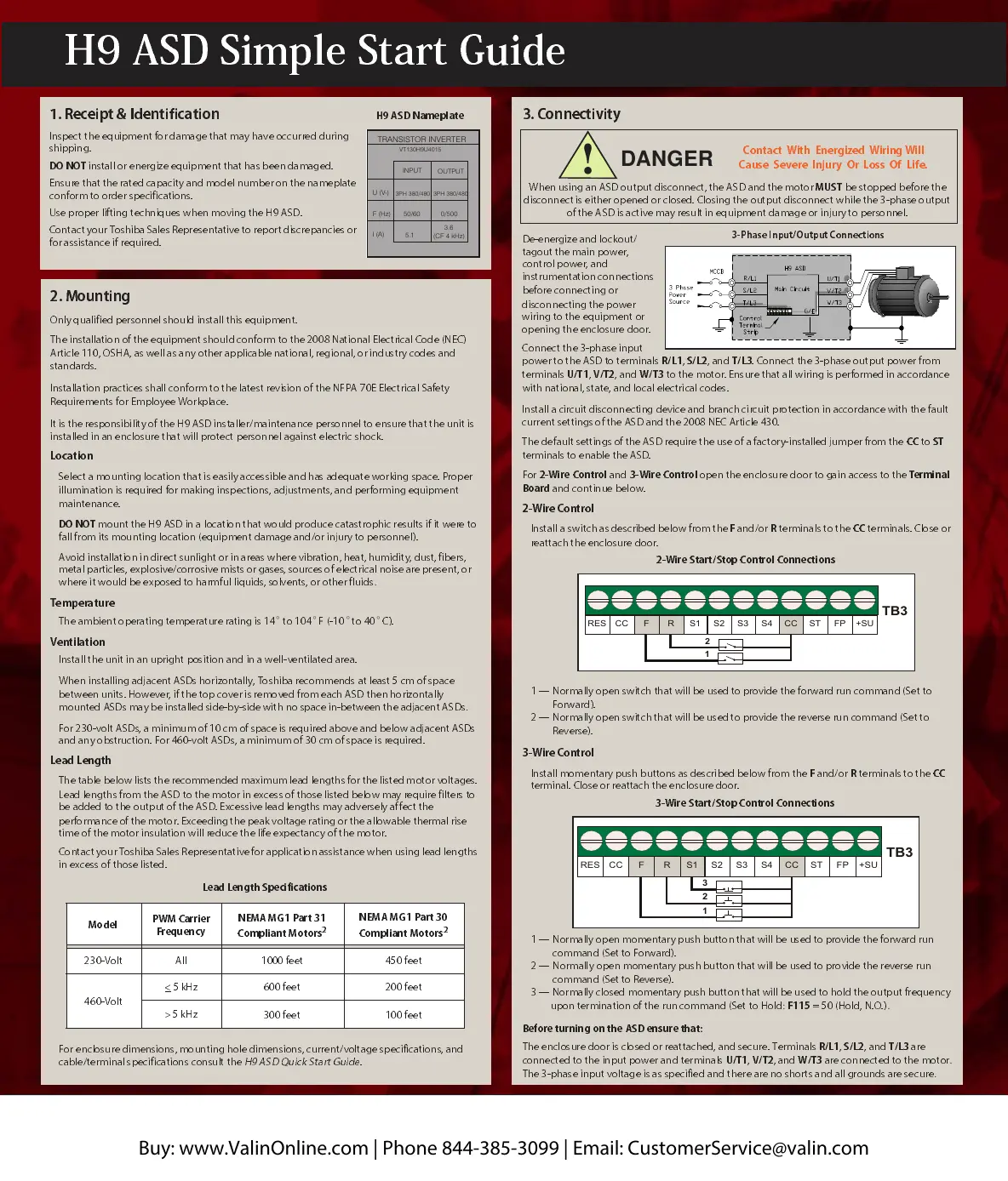
3. Connectivity
Contact
With
Energized
Wiring Will
Cause
Severe
Injury
Or
Loss
Of
Life.
DANGER
!
When using an ASD output disconnect, the ASD and the motor
MUST
be stopped before the
disconnect is either opened or closed. Closing the output disconnect while the 3-phase output
of the ASD is active may result in equipment damage or injury to personnel.
De-energize and lockout/
tagout the main power,
control power, and
instrumentation connections
before
connecting or
disconnecting the power
wiring to the equipment or
opening the enclosure
door.
Connect the 3-phase input
power to the ASD to terminals
R/L1
,
S/L2
, and
T/L3
. Connect the 3-phase output power from
terminals
U/T1
,
V/T2
, and
W/T3
to the
motor. Ens ure that all wiring is performed in accordance
with
national, state, and local electrical codes.
Install a circuit disconnecting device and branch circuit protection in accordance with the fault
current settings of the ASD and th e 2008 NEC Ar ticle 430.
The default settings of the ASD require the use of a factory-installed jumper from
the
CC
to
ST
terminals to e nable the ASD.
For
2-Wire Control
and
3-Wire Control
open the enclosure
door to gain access to the
Terminal
Board
and continue below.
2-Wire Control
Install
a switch as described below from the
F
and/or
R
terminals to the
CC
terminals. Close or
reattach the en closu re d oor.
1 — Nor mally
open
switch that will be used to provide the forward run command (Set to
Forward).
2 — Normally
open switch tha t will be used to provide the reve rse run com m an d (Set to
Reverse).
3-Wire Control
Install momentary push bu ttons as des cribed below from the
F
and/or
R
terminals to the
CC
terminal. Close or reatta ch the enclosure door.
1 — Nor mally
open
momentary push button that will be used to provide the forward run
command (Set to Forward).
2
— Normally
open
momen ta ry push button that will be u sed to provide the reverse run
command (Set to Reverse).
3 — Norm ally
closed
momen tar y push butto n that w ill be used to hold the outp ut frequency
upon termination of the run command (Set to Hold
:
F115
= 50 (Hold, N.O.)
.
Bef o re tu rning o n the AS D ensu r e tha t:
The enclosure door is closed or reattached, and secure.
Terminals
R/L1
,
S/L2
, and
T/L3
are
connected to the
input power
and
terminals
U/T1
,
V/T2
, and
W/T3
are connected to the motor
.
The 3-phase inpu t voltag e is as specified
and
there are no shorts and all grounds are secure
.
RES
CC
F R S1 S2 S3 S4 CC ST FP +SU
1
2
3
TB3
3-Wire Sta rt/St op C ontr ol C onnections
3-Phase Input/Output Connections
2-Wire Start/Stop Control Connections
RES
CC
F S1 S2 S3 S4 CC ST FP +SU
TB3
R
1
2
1. Receipt & Identifica tion
Inspect the equipmen t fo r damag e that ma y have occu rred du ring
shipping.
DO NOT
install or energize equipment that has been damaged.
Ensure that the rated capacity and model number on the nameplate
conform to order specifications.
Use proper lifting techniq ues when moving the H9 ASD.
Contact your Toshiba Sales Representative to report discrepancies or
for assista nce if required.
H9 ASD Name plate
2. Mounting
Only qualified personnel should install this equipment.
The installation of the equipment should conform to the 2008 National Electrical Code
(NEC)
Article 110, OSHA, as well as any oth er applicable nationa l, regional, o r industry cod es and
standards.
Installation pr acti ces sh all con for m to the la test rev ision of
the
NFPA 70E Electrical Safety
Requirements for Employee Workplace.
It is the responsibility of the H9 ASD insta ller/ main tenan ce personne l to ensu re that the unit is
installed in an enclosure that will protect personnel against electric shock.
Location
Select a mounting location tha t is easily accessible and
has adequate working space. Proper
illumination is required for making in specti ons,
adjustments, and performing equipment
maintenance.
DO NOT
mount the H9
ASD in a locatio n that would produce catastrophic results if it were to
fall from its mounting location (eq uipment damage and/or injury to personnel).
Avoid installation in direct sunlight or in areas where vibration, heat, humidity, dust, fibers,
metal particles, explosive/corrosive mists or ga ses, sources of electrical nois e are presen t, or
where it would be exposed to harmful liquids, solvents, or other fluids
.
Temperature
The amb ien t o pe ra t in g t e mper a t ur e rat in g is 1 4
to 104
F
(-10
to 40
C).
Ventilation
Install the unit in an upright position
and in a well-ventilated area.
When installing adjacent ASDs horizontally, Toshiba recommends
at least 5 cm of space
between units. Howev er, if the top cover is removed from each ASD then horizont ally
moun t ed ASDs may b e inst a lled sid e-b y- sid e wit h no space i n- bet w een th e adj a cen t A SDs
.
For 230- v olt ASDs, a m in imu m of 10 cm of space i s requ ir ed abov e an d be lo w adj a cen t A SDs
and any obstruction. For 460-volt ASDs, a minimum of 30 cm of space is required.
Lead Length
The table
below lists the recommended maximum lead lengths for the listed motor voltages.
Lead lengths from the ASD to the motor in excess of those listed below may require filters to
be added to the output of the ASD.
Excessive lead leng ths may adv ersely affect the
performance of the motor. Exceedin g the peak voltage rating or the allow able therm al rise
time of the motor insulation will reduce the life expectancy of the motor.
Contact your Toshiba Sales Representative for application assistance when using lead lengths
in excess of those listed.
For enclosure dimensions, mounting hole dimensions, current/voltage specifications, and
cable/termin al specifications consult the
H9 ASD Quick Start Guide
.
Model
PWM Carrier
Frequ e ncy
NEMA MG1 Part 31
Complia nt M otors
2
NEMA MG1
Part 30
Compliant Motors
2
230-Volt All 1000 feet 450 feet
460-Volt
< 5 kHz 600 feet 200 feet
>
5 kHz
300 feet 100 feet
Lead Length Specifications
H9 ASD Simple Start Guide
TRANSISTOR INVERTER
VT130H9U4015
INPUT
OUTPUT
U (V-)
F (Hz)
I (A)
50/60
0/500
5.1
3.6
(CF 4 kHz)
3PH 380/480 3PH 380/480
° ° °°
Buy: www.ValinOnline.com | Phone 844-385-3099 | Email: CustomerService@valin.com
 Loading...