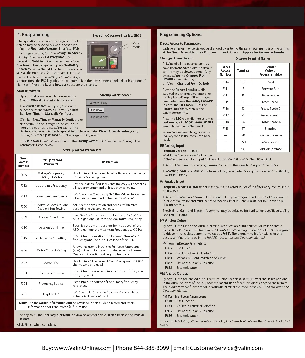
Electronic Operato r Interface (EO I)
Rotary
Encoder
Wizard: RunWizard: Run
Run nowRun now
Run next timeRun next time
Manually configure (Finish)Manually configure (Finish)
Startup Wizard Screen
4. Programmi ng
The operating parameters displayed on the LCD
screen may be selected, viewed, or changed
using the
Electronic Operator Interface
(EOI).
To change a setting turn the
Rotary Encoder
to
highlight the desired
Primary Menu
item
(repeat for
Sub Me nu
items as required). Select
the item to be changed and press the
Rotary
Encoder
to enter the
Edit
mode — the encoder
acts as the enter key.
Set the parameter to the
new value. To exit the setting without saving a
change press the
ESC
key while the parameter is in the reverse video mode (dark background/
light text).
Press the
Rotary Enco der
to accept the chan ge.
Startup Wizard
Upon in itia l power up or factory reset the
Startup Wizard
will start auto matically.
The
Startup Wizard
will query the user to
select one o f th e following items:
Run No w
,
Run Next Time
, or
Ma nu ally Co nf igur e
.
Click
Run Ne xt Time
or
Ma nu ally Co nf igur e
to
skip setup. The ASD may a lso be setup at a
lat e r time b y dire ctl y access in g each of th e
startup parameters via the
Program Menu
, the associated
Direct Access Number
, or by
running the
Startup Wizard
from the programming menu.
Click
Run Now
to setup the ASD now. The
Startup Wizard
will take the user through the
parameters listed belo w.
At any poin t, the us er ma y click
Next
to skip a param eter or cli ck
Finish
to close the
Startup
Wizard
.
Click
Finish
when complet e.
Startup Wizard Parameters
Direct
Access
Number
Startup Wizard
Parameter
Description
F405
Voltage/Frequency
Rating of Motor
Used to input the nameplated voltage and frequ ency
of the motor being used.
F012 Upper Limit Frequency
Sets the highest frequency that the ASD will accept as
a frequency command or frequency setpoint.
F013 Lower Limit Frequency
Sets the lowest frequency t ha t the ASD will accept as
a frequency command or frequency setpoint.
F000
Automatic Acceleration/
Deceleration Setting
Adjusts the acceleration and deceleration rates
according to the applied load.
F009 Acceleration Time
Specifies the time in seconds for the output of the
ASD to go from 0.0 Hz to the Ma ximum Frequency.
F010 Deceleration Tim e
Specifies the time in seconds for the output of the
ASD to go from the Maximu m Freque ncy to 0.0 Hz.
F015 Volts per Hertz Setting
Establishes the relationship between the output
frequency and the output voltage of the ASD.
F406 Motor Current Rating
Allows the u ser to input the Full-Load Amperage
(FLA) of the motor. Used to determine the Thermal
Overload Protection setting for the motor.
F407 Motor RPM
Used to input the nameplated rated speed (RPM) of
the motor being used.
F003 Command Source
Establishes the source of input commands (i.e., Run,
Stop, Jog, etc.).
F004 Frequency Source
Establishes the source of the primary frequency
reference.
F701 Display Unit
Sets the unit of measure for current and voltage
values displayed on t he EOI.
Note
:
Use the
Motor Information
outline provided in this guide to record and retain
information about the motor for future use.
Programming Options:
Direct Access to Parameters
Each parameter may be viewed or changed by entering the parameter number of the setting
at the
Direct Access
Menu
via Program
Direct Access
Applic a ble Pa r am et er Nu mb er
.
Changed From Default
A listing of all the
parameters that
have been changed from the default
setting may be viewed sequentially
by accessing the
Changed From
Def au lt
screen
via
Program
Utilities
Changed From Default.
Press the
Rotary Encoder
while
stopped at a changed parameter to
display the settings of the changed
parameter. Press the
Rotary Encoder
to enter the
Edit
mode. Turn the
Rotary Encoder
to change the
parameter setting.
Press the
ESC
key while the system is
performing a
Cha nged Fro m De f au lt
search to terminate the search.
When finis hed sear ching, pre ss the
ESC
key to take the menu back one
level.
RR Analog Input
Frequ enc y Mo de 1
(
F004
)
establishes the user-selected source
of the frequency-cont rol in put for t he ASD. By default it is set to the RR terminal.
This input terminal may be programmed to control the speed or torque of the motor
.
The
Scaling
,
Gain
, and
Bias
of this terminal may be adjusted for application-specific suitability
(see
F210
–
F215
).
V/I Analog Input
Frequ enc y Mode 1
(
F004
)
establishes the user-selected source of the frequency-control input
for the ASD.
This is an isolated input terminal. This terminal may be programmed to contro l the speed or
torque of the motor and must be set to receive either current (
SW301
set to
I
) or voltage
(
SW301
set to
V
).
The
Scaling
,
Gain
,
and
Bias
of this terminal may be adjusted for application-specific suitability
(see
F201
–
F206
).
FM Analog Output
By default, the
FM
analog
output terminal produces an output current or voltage that is
proportional to the output frequency of the ASD or of the magnitude of the function assigned
to this terminal (select current or voltage at
F681
). The programmable functions for this
output terminal are listed in the
H9 ASD Installation and Operation Manual
.
FM
Terminal Setup Paramete
rs:
F005
— Set Function
F006
— Calibrate Terminal Selection
F681
— Voltage/Curr ent Switching Selection
F682
— Response Polarity Selection
F683
— Bias Adju stm ent
AM Analog Output
By default, the
AM
analog
output terminal produces an 0-20
mA curre nt that is proportional
to the output current of the ASD or of the magnitude of the function assigned to the terminal.
The programmable functions for this output terminal are listed in the
H9 ASD Installation and
Operation Manual
.
AM Termin al Setup Paramete
rs:
F670
— Set Function
F671
— Calibrate Terminal Selection
F685
— Response Polarity Selection
F686
— Bias Adjustment
For a complete listing of the discrete and analog inputs and outputs see the
H9
ASD Quick Start
Guide
.
Discrete
Terminal Name s
Direct
Access
Numb er
Terminal
Default
(Where
Programmable)
F114 RES Reset
F111 F Forward Run
F112 R Reverse Run
F115 S1 Pr eset Speed 1
F116 S2 Pr eset Speed 2
F117 S3 Pr eset Speed 3
F118 S4 Pr eset Speed 4
F113 ST Standby
— FP Frequency Pulse
— +SU References CC
— CC Control Common
Buy: www.ValinOnline.com | Phone 844-385-3099 | Email: CustomerService@valin.com
 Loading...