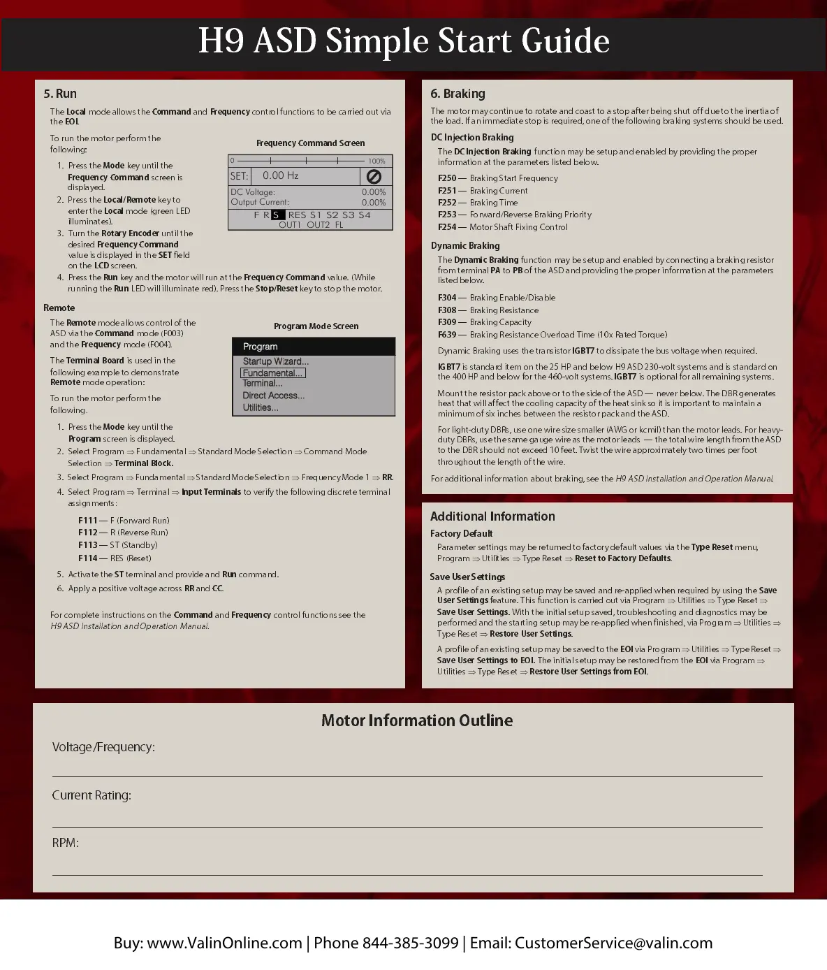
5. Run
The
Local
mode a llows the
Command
and
Frequ e nc y
control functions to be carried out via
the
EOI
.
To run
the motor
perform the
following :
1. Press the
Mode
key until the
Frequ enc y Co m man d
screen is
displayed.
2. Press the
Loc
al/Remote
key to
enter the
Local
mode (green LED
illuminates).
3. Turn the
Ro
tary Encoder
until the
desired
Frequ e nc y Co mma nd
value is displa yed in the
SET
field
on the
LCD
screen.
4. Press the
Run
key and the motor will
run at the
Frequ e ncy Com ma nd
value.
(While
running the
Run
LED will illu minate red). Press the
Stop/Reset
key
to stop
the
motor.
Remote
The
Remote
mode allows control of the
ASD via the
Command
mode
(
F003)
and the
Frequ enc y
mode (F004).
The
Terminal Board
is used in the
following example to demonstrate
Remote
mode operation:
To run
the motor
perform the
following
.
1. Press the
Mode
key unt il the
Program
screen is displayed .
2. Select Program
Fundamental
Standard Mode Selection
Command Mode
Selection
Terminal Bloc k.
3.
Select Program
Fundamental
Standard Mode Selection
Frequency Mode 1
RR
.
4. Select Program
Terminal
Input Term inals
to verify the fo llowing discrete terminal
assignments
:
F111
— F (Forward Run)
F112
— R (Re verse Run)
F113
—
ST (Standby)
F114
— RES (Rese t)
5. Activate the
ST
terminal and provide and
Run
command.
6. Apply a positive voltage acro ss
RR
and
CC
.
For complete instructions on the
Command
and
Frequ en cy
control functions
see the
H9 ASD Installa tion an d Oper ation Ma nua l.
Frequ e nc y Co mm and Sc r ee n
0
100%
SET:
DC Voltage:
Output Current:
0.00%
0.00%
0.00 Hz
OUT1 OUT2 FL
F R RES S1 S2 S3 S4ST
Startup Wizard...Startup Wizard...
Terminal...Terminal...
ProgramProgram
Direct Access...Direct Access...
Utilities...Utilities...
Fundamental...Fundamental...
Additional Information
Factory Default
Parameter
settings may be returned to factory default values via the
Type Reset
menu,
Program
Utilities
Type Reset
Reset to Fa ct o ry De f au lt s
.
Save User Settings
A profile of an existing setup may be saved and re-applied when required by using the
Save
User Settings
feature. This function is carried out via Program
Utilities
Type Reset
Save User Settings
. With the initial setup saved, troubleshooting and diagnostics may be
performed and the starting setup may be re-applied when finished, via Program
Utilities
Type Reset
Restore User Settings
.
A profile of an existing setup may be saved to the
EOI
via
Program
Utilities
Type Reset
Save User Settings
to EO I.
The initial setup may be restored from the
EOI
via Program
Utilities
Type Reset
Restore User Settings from EOI
.
6. Braking
The motor may continue to rotate and coast to a stop after being shut off due to the inertia of
the load. If an immediate stop is required, one of the following braking systems should be used.
DC Injection Braking
The
DC Injection Braking
function may be setup and enab led by providing the proper
information at the parameters listed below.
F250
— Braking Start Frequency
F251
— Brak ing Current
F252
— Brak ing Ti me
F253
— Forward/Reverse Braking Priority
F254
— Motor Shaft Fixing Control
Dynamic Braking
The
Dynamic Braking
function may be setup and enabled by connecting a braking resistor
from terminal
PA
to
PB
of the ASD and pro viding the pr oper in formation at the par amet ers
listed
below.
F304
— Braking En able /Disa b le
F308
— Brak ing R esistance
F309
— Brak ing C apaci ty
F639
— Braking R esistance Overload Time (1 0x Ra ted Torqu e)
Dynamic Braking uses the transistor
IGBT7
to dissipate the bus voltage when required.
IGBT7
is standard item on the 25 HP and below H9 ASD 2 30- volt systems a nd is stand ard on
the 400 HP and below for the 460-volt systems.
IGBT7
is optional for all remaining systems.
Mount the resistor pack above or to the side of the ASD — never below. The DBR generates
heat that will af fect the cooling capacity of the heat sink so it is important to maintain a
mini mu m of six in ch es b et we en the res ist o r pack an d the ASD.
For light-duty DBRs, use one wire size smaller (AWG or kcmil) than the motor leads. For heavy-
duty DBRs, use the same gauge wire as the motor leads — the total wire length from the ASD
to the DBR should no t exceed 10 f eet. Tw ist
the wire approximately two times per foot
throughout the length of the wire
.
For additional information about braking, see the
H9
ASD Installation and Operation Manual
.
Motor Information Outline
Voltage/Frequency:
Current Rating:
RPM:
H9 ASD Simple Start Guide
Buy: www.ValinOnline.com | Phone 844-385-3099 | Email: CustomerService@valin.com
 Loading...