EasyManua.ls Logo

Toshiba MCY-MHP0305HT-C User Manual

Toshiba MCY-MHP0305HT-C
162 pages
To Next Page IconTo Next Page
Page #1 background imageLoading...
Page #1 background image
FILE NO. A10-1421
Revision1: Oct. 2015
SERVICE MANUAL
AIR-CONDITIONER (MULTI TYPE)
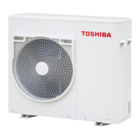
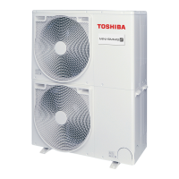
㪬㪫㪛㪦㪦㪩㩷㪬㪥㪠㪫
Model name:
This service manual provides relevant explanations about new outdoor unit.
Please refer to the following service manuals for each indoor units.
MCY-MHP0305HT-C/0405HT-C/0505HT-C
MCY-MHP0305HT/0405HT
MCY-MHP0305HT-ID/0405HT-ID
MCY-MHP0305HT-CF/0405HT-CF/0505HT-CF
<4-way Cassette Type>
(MMU-AP㪁㪁㪁㪁H) A08-004 A08-004
(MMU-AP㪁㪁㪁㪁H-C) A08-004 A11-008
(MMU-AP㪁㪁㪁4HP) (Made in Thailand model) SVM-13011 SVM-13011
(MMU-AP㪁㪁㪁4HY-C) (Made in China model) A10-1402 A10-1402
<2-way Cassette Type>
(MMU-AP㪁㪁㪁㪁WH) A10-007 A10-007
(MMU-AP㪁㪁㪁㪁WH-C) A10-007 A11-008
<Concealed Duct Standard Type>
(MMD-AP㪁㪁㪁4BH-C) A10-033 A11-008
(MMD-AP㪁㪁㪁6BH) SVM-13087 SVM-13087
(MMD-AP㪁㪁6BHY-C) (Made in China model) A10-1415 A10-1415
<Slim Duct Type>
(MMD-AP㪁㪁㪁4SPH) A12-005 A12-005
(MMD-AP㪁㪁㪁4S(P)H-C) A12-005 A11-008
(MMD-AP㪁㪁㪁6M(P)HY-C) (Made in China model) A10-1403 A10-1403
<High-wall Type>
(MMK-AP㪁㪁㪁3H) (Made in Thailand model) A10-034 A10-034
<Console Type>
(MML-AP㪁㪁㪁㪁NH) (Made in Thailand model) SVM-11036 SVM-11036
<Ceiling Type>
(MMC-AP㪁㪁㪁7HP) (Made in Thailand model) SVM-13085 SVM-13085
<Other indoor units>
(MM-AP㪁㪁㪁㪁㪁H) (Made in Japan model) A10-033 A10-033
(MM-AP㪁㪁㪁㪁㪁H-C) (Made in China model) A10-033 A11-008
SVMA-07010 SVMA-07010
Service contents Service parts

Table of Contents

Question and Answer IconNeed help?

Do you have a question about the Toshiba MCY-MHP0305HT-C and is the answer not in the manual?

Toshiba MCY-MHP0305HT-C Specifications

General IconGeneral
BrandToshiba
ModelMCY-MHP0305HT-C
CategoryAir Conditioner
LanguageEnglish

Summary

1 Product summary

1-1. Outdoor unit

Details about the outdoor unit specifications, including power supply, model names, and capacities.

1-2. Connectable indoor units

Lists various indoor unit types and their corresponding model names that can be connected.

1-3. Branching joints and headers

Information on specific connection components like Y-shape branching joints and headers.

1-4. PMV kit

Details about the Pulse Motor Valve (PMV) kit, including model types and capacity ranges.

2 Construction views

3 Wiring diagram

4 Parts rating

4-1. Outdoor unit

Lists the specifications and ratings for various components of the outdoor unit.

4-2. Outdoor inverter

Details the specifications and ratings for the components within the outdoor inverter assembly.

4-3. Parts layout in outdoor unit

Illustrates the physical location of components within the outdoor unit.

4-4. Parts layout in inverter assembly

Shows the arrangement of components within the inverter assembly.

5 Refrigerant piping systematic drawing

6 Control outline

6-1. Outdoor unit

Explains the control logic and operation for the outdoor unit's functions.

7 Applied control for outdoor unit

7-1. Outdoor fan high static pressure shift

Describes how to adjust the outdoor fan for high static pressure situations, often related to duct installation.

7-2. Priority operation mode setting

Explains how to set priority modes for cooling, heating, or specific indoor units.

7-3. Applied control of outdoor unit

Details various applied control functions for the outdoor unit.

8 Test operation

8-1. Procedure and summary of test operation

Outlines the steps and overall process for conducting a test operation of the air conditioner system.

8-2. Check items before test operation (before powering-on)

Lists essential checks to perform before powering on the system for test operation.

8-3. Check at main power-on

Details checks to perform on both indoor and outdoor units immediately after main power is turned on.

8-4. Address setup

Explains the process of setting up addresses for indoor and outdoor units, crucial for system communication.

8-5. Troubleshooting in test operation

Provides guidance for diagnosing and resolving issues encountered during test operation.

8-6. Test operation check

Details specific checks to perform during the test operation phase.

9 Troubleshooting

9-1. Overview

Provides a general introduction to troubleshooting, including applicable models and necessary tools.

9-2. Troubleshooting method

Explains how to identify faults using displayed check codes on controllers and outdoor units.

9-3. Troubleshooting based on information displayed on remote controller

Details how to use remote controller displays and error history for troubleshooting.

9-4. Check codes displayed on remote controller and outdoor unit (7-segment display on I/F board) and locations to be checked

Lists check codes from various displays and their corresponding locations and causes.

9-5. Diagnosis procedure for each check code

Provides step-by-step diagnostic flowcharts for specific check codes.

10 Outdoor unit parts replacement methods

10-1. Common

Covers general procedures and precautions for replacing common parts of the outdoor unit.

10-2. Discharge cabinet

Details the steps for detaching and attaching the discharge cabinet of the outdoor unit.

10-3. Side panel

Explains the procedure for removing and installing the side panel of the outdoor unit.

11 P.C. board exchange procedures

11-1. Interface P.C. board replacement procedure

Provides a step-by-step guide for replacing the interface P.C. board, including applicable models.

11-2. IPDU P.C. board replacement procedure

Details the process for replacing the IPDU P.C. board, including applicable models and safety precautions.

12 Exploded diagram / parts list

MCY-MHP0305HT-C/0405HT-C/0505HT-C MCY-MHP0305HT/0405HT MCY-MHP0305HT-ID/0405HT-ID MCY-MHP0305HT-CF/0405HT-CF/0505HT-CF

Lists applicable model names for which the exploded diagram and parts list are provided.
Related product manuals