B
barbarabutlerAug 20, 2025
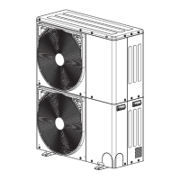
How to troubleshoot outdoor unit fan trouble in Toshiba MCY-MUG0401HSW-E?
- ZzjohnsonAug 20, 2025
If your Toshiba Air Conditioner displays an error related to the outdoor unit fan, inspect and test the operation of the fan components.