EasyManua.ls Logo

Toshiba MMD-UP0271BHP-E User Manual

Toshiba MMD-UP0271BHP-E
295 pages
To Next Page IconTo Next Page
Page #1 background imageLoading...
Page #1 background image
AIR CONDITIONER (MULTI TYPE)
SERVICE MANUAL
Indoor unit
<4-way cassette type>
MMU-UP0091HP-E(TR)
MMU-UP0121HP-E(TR)
MMU-UP0151HP-E(TR)
MMU-UP0181HP-E(TR)
MMU-UP0241HP-E(TR)
MMU-UP0271HP-E(TR)
MMU-UP0301HP-E(TR)
MMU-UP0361HP-E(TR)
MMU-UP0481HP-E(TR)
MMU-UP0561HP-E(TR)
<Ceiling type>
MMC-UP0151HP-E(TR)
MMC-UP0181HP-E(TR)
MMC-UP0241HP-E(TR)
MMC-UP0271HP-E(TR)
MMC-UP0361HP-E(TR)
MMC-UP0481HP-E(TR)
MMC-UP0561HP-E(TR)
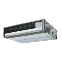
<Concealed Duct Standard type>
MMD-UP0051BHP-E
MMD-UP0071BHP-E(TR)
MMD-UP0091BHP-E(TR)
MMD-UP0121BHP-E(TR)
MMD-UP0151BHP-E(TR)
MMD-UP0181BHP-E(TR)
MMD-UP0241BHP-E(TR)
MMD-UP0271BHP-E(TR)
MMD-UP0301BHP-E(TR)
MMD-UP0361BHP-E(TR)
MMD-UP0481BHP-E(TR)
MMD-UP0561BHP-E(TR)
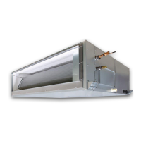
<Concealed Duct High Static Pressure type>
MMD-UP0181HP-E(TR)
MMD-UP0241HP-E(TR)
MMD-UP0271HP-E(TR)
MMD-UP0361HP-E(TR)
MMD-UP0481HP-E(TR)
MMD-UP0561HP-E(TR)
MMD-UP0721HP-E(TR)
MMD-UP0961HP-E(TR)
<Concealed Duct High Static Pressure
fresh air intake type>
MMD-UP0481HFP-E(TR)
MMD-UP0721HFP-E(TR)
MMD-UP0961HFP-E(TR)
MMD-UP1121HFP-E(TR)
MMD-UP1281HFP-E(TR)
<Console type>
MML-UP0071NHP-E(TR)
MML-UP0091NHP-E(TR)
MML-UP0121NHP-E(TR)
MML-UP0151NHP-E(TR)
MML-UP0181NHP-E(TR)
<High wall type>
MMK-UP0031HP-E(TR)
MMK-UP0051HP-E(TR)
MMK-UP0071HP-E(TR)
MMK-UP0091HP-E(TR)
MMK-UP0121HP-E(TR)
MMK-UP0151HP-E(TR)
MMK-UP0181HP-E(TR)
MMK-UP0241HP-E(TR)
MMK-UP0031HPL-E(TR)
MMK-UP0051HPL-E(TR)
MMK-UP0071HPL-E(TR)
MMK-UP0091HPL-E(TR)
MMK-UP0121HPL-E(TR)
MMK-UP0151HPL-E(TR)
MMK-UP0181HPL-E(TR)
MMK-UP0241HPL-E(TR)
FILE NO. SVM-20095
January, 2021

Table of Contents

Other manuals for Toshiba MMD-UP0271BHP-E

Questions and Answers:

Toshiba MMD-UP0271BHP-E Specifications

General IconGeneral
BrandToshiba
ModelMMD-UP0271BHP-E
CategoryAir Conditioner
LanguageEnglish

Summary

PRECAUTIONS FOR SAFETY

SPECIFICATIONS

CONSTRUCTION VIEWS (EXTERNAL VIEWS)

WIRING DIAGRAMS

3-1. 4-way cassette type

Wiring diagram for 4-way cassette type indoor units, illustrating connections for various components and controls.

3-2. Ceiling type

Wiring diagram for ceiling type indoor units, illustrating connections for various components and controls.

3-3. Concealed Duct Standard type

Wiring diagram for concealed duct standard type indoor units, illustrating connections for various components and controls.

3-4. Concealed Duct High Static Pressure type

Wiring diagram for concealed duct high static pressure type indoor units, illustrating connections for various components and controls.

3-5. Concealed Duct High Static Pressure fresh air intake type

Wiring diagram for concealed duct high static pressure fresh air intake type indoor units, illustrating connections.

3-6. Console type

Wiring diagram for console type indoor units, illustrating connections for various components and controls.

3-7. High wall type

Wiring diagram for high wall type indoor units, illustrating connections for various components and controls.

COMMUNICATION TYPE, MODEL NAMES AND THE MAXIMUM NUMBER OF CONNECTABLE UNITS

APPLIED CONTROL AND FUNCTIONS (INCLUDING CIRCUIT CONFIGURATION)

8-4. Indoor Print Circuit Board

Detailed view of indoor print circuit boards (MCC-1643, MCC-1720, MCC-1696) with component identification.

8-5. Test run of indoor unit

Procedure for performing a cooling/heating test run of the indoor unit using wired or wireless remote controllers.

8-6. Method to set indoor unit function DN code

Procedure for setting indoor unit functions using DN codes via wired remote controller.

TROUBLESHOOTING

9-1. Overview

General overview of troubleshooting, applicable models, required tools, and normal behaviors to check.

9-2. Troubleshooting method

Method for identifying trouble sites using check codes displayed on remote controllers, outdoor units, and indicator lights.

9-3. Troubleshooting based on information displayed on remote controller

Procedure for accessing and interpreting check codes and trouble history displayed on the remote controller.

9-4. Check Codes Displayed on Remote Controller and SMMS series Outdoor Unit (7-Segment Display on I/F Board) and Locations to Be Checked

Detailed list of check codes, their locations, descriptions, system status, detection conditions, and check items.

9-5. Diagnostic Procedure for Each Check Code (Indoor Unit)

Flowcharts for diagnosing specific indoor unit check codes like E01, E02, E03, E04, E08, E10, E11, E18, F01, F02, F03, F10, F29, F30.

P.C. BOARD EXCHANGE PROCEDURES

EXPLODED VIEWS AND PARTS LIST

Related product manuals