Do you have a question about the Toshiba MMD-UP0361BHP-TR and is the answer not in the manual?
Specifications for the 4-way cassette type indoor unit, covering capacity, electrical characteristics, dimensions, and sound levels.
Specifications for the ceiling type indoor unit, detailing capacity, electrical, dimensions, and sound performance.
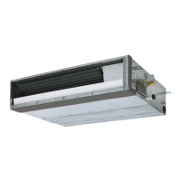
Specifications for the concealed duct standard type indoor unit, including capacity, electrical, dimensions, and sound.
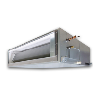
Specifications for concealed duct high static pressure units, covering capacity, electrical, dimensions, and sound.
Specifications for concealed duct high static pressure units with fresh air intake, including capacity and electrical data.
Specifications for console type indoor units, detailing capacity, electrical characteristics, dimensions, and sound levels.
Specifications for high wall type indoor units, covering capacity, electrical, dimensions, and sound.
External views and dimensions for the 4-way cassette type indoor unit, including installation space requirements.
External views and dimensions for the ceiling type indoor unit, detailing installation space and component layout.
External views and dimensions for concealed duct standard type units, including installation space and dimensions.
External views and dimensions for concealed duct high static pressure units, detailing installation requirements.
External views and dimensions for concealed duct high static pressure units with fresh air intake.
External views and dimensions for console type indoor units, including installation space and mounting details.
External views and dimensions for high wall type indoor units, covering installation space and mounting.
Wiring diagram for the 4-way cassette type indoor unit, illustrating connections between components.
Wiring diagram for the ceiling type indoor unit, showing electrical connections and component layout.
Wiring diagram for concealed duct standard type units, detailing electrical connections for the indoor unit.
Wiring diagram for concealed duct high static pressure units, illustrating electrical connections.
Wiring diagram for concealed duct high static pressure units with fresh air intake.
Wiring diagram for console type indoor units, showing electrical connections and component layout.
Wiring diagram for high wall type indoor units, illustrating electrical connections.
Explanation of the functional parts within the indoor unit's refrigerant cycle diagram.
Control behavior when the air conditioner power supply is reset, including unit distinction and setting retention.
Details on selecting operation modes via the remote controller, including available commands and outlines.
Specifies the adjustment range for room temperature control via remote controller for different unit types.
Describes how operation capacity is determined by the outdoor unit based on TA and Ts differences.
Explains the judgment for selecting COOL/HEAT based on temperature differences and thermostat settings.
Details on selecting fan speed via remote control and AUTO mode based on temperature differences.
Describes how TC2 and TCJ sensor temperatures influence fan tap selection and cold air prevention.
Explains freeze prevention control logic based on TC1, TC2, and TCJ sensor readings during cooling operation.
Details controls for refrigerant/oil recovery during stop/thermostat OFF/FAN operation in cooling mode.
Details controls for refrigerant/oil recovery during stop/thermostat OFF/FAN operation in heating mode.
Describes forced operation continuation for 3 minutes after start, even in thermostat-OFF condition.
Explains the operation of the drain pump during cooling, DRY, and stop statuses, including float switch logic.
Describes the indoor fan operation after the unit stops from HEAT operation.
Details ON/OFF operation control via HA signal from remote site or remote ON/OFF interface.
Configuration for alarm output from indoor P.C. board for header and follower units.
Explanation of how the filter sign is displayed on the remote controller based on elapsed time.
Indicates when specific operational statuses like READY or HEAT READY are displayed on the remote controller.
Describes selection of controllable functions via remote controller based on central controller settings.
Details on louver position setup, swing modes, and individual air direction adjustments.
Information on the DC motor's operation and check codes related to its function.
Explains the power saving operation, its limitations, and how settings are retained.
Details on communication types (TU2C-Link, TCC-Link) and corresponding model names for units and controllers.
Wiring specifications and connectable unit limits when combining TU2C-Link and TCC-Link systems.
Block diagram for indoor controller MCC-1643, detailing connections for wired remote controllers.
Block diagram for indoor controller MCC-1720, illustrating connections for wired remote controllers.
Block diagram for indoor controller MCC-1696, detailing wired remote controller connections.
Overview of indoor print circuit boards, detailing component locations and connections for various models.
Procedure for performing cooling/heating test runs using wired or wireless remote controllers.
Instructions for setting indoor unit functions and DN codes using a wired remote controller.
Details on control systems using remote location ON/OFF control boxes and their wiring.
General overview of troubleshooting, applicable models, required tools, and normal behaviors.
Methodology for identifying trouble sites using check codes detected by various devices.
Procedure for troubleshooting based on check codes and trouble history displayed on the remote controller.
Detailed list of check codes from remote controller and outdoor unit displays with corresponding locations to check.
Flowcharts for diagnosing check codes related to indoor units, guiding troubleshooting steps.
Graphs and tables showing the resistance characteristics of indoor unit sensors (TA, TC1, TC2, TCJ).
Recommended maintenance checklist for indoor and outdoor units, including cleaning and inspection items.
Procedures for replacing indoor unit P.C. boards, including EEPROM data handling and setting verification.
Procedures for detaching and attaching components of the 4-way cassette type indoor unit.
Procedures for detaching and attaching components of the ceiling type indoor unit.
Procedures for detaching and attaching components of the concealed duct standard type indoor unit.
Procedures for detaching and attaching components of concealed duct high static pressure units.
Procedures for detaching and attaching components of concealed duct high static pressure units with fresh air intake.
Procedures for detaching and attaching components of the console type indoor unit.
Procedures for detaching and attaching components of the high wall type indoor unit.
Exploded view and parts list for the 4-way cassette type indoor unit.
Exploded view and parts list for the ceiling type indoor unit.
Exploded view and parts list for the concealed duct standard type indoor unit.
Exploded view and parts list for concealed duct high static pressure units.
Exploded view and parts list for concealed duct high static pressure units with fresh air intake.
Exploded view and parts list for console type indoor units.
Exploded view and parts list for high wall type indoor units.
| Brand | Toshiba |
|---|---|
| Model | MMD-UP0361BHP-TR |
| Category | Air Conditioner |
| Language | English |