A
Alexandria BestJul 28, 2025
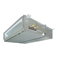
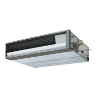
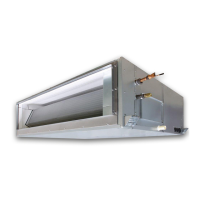
Why is my Toshiba MMD-UP0091BHP-E Air Conditioner performing poorly?
- JjessicafitzgeraldJul 28, 2025
Poor performance of your Toshiba Air Conditioner can be due to a failure to regularly clean both the indoor and outdoor units.