AIR CONDITIONER (MULTI TYPE)
SERVICE MANUAL
FILE No. A10-033-1
This service manual provides relevant explanations about new indoor unit (4 series). Please refer to
the following service manuals for each indoor units.
Indoor unit
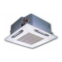
<1-way Cassette Type (YH, SH)>
MMU-AP0074YH-E(-TR)
MMU-AP0094YH-E(-TR)
MMU-AP0124YH-E(-TR)
MMU-AP0154SH-E(-TR)
MMU-AP0184SH-E(-TR)
MMU-AP0244SH-E(-TR)
<Concealed Du ct Hig h Static
Pressu re Type>
MMD-AP0184H-E(-TR)
MMD-AP0244H-E(-TR)
MMD-AP0274H-E(-TR)
MMD-AP0364H-E(-TR)
MMD-AP0484H-E(-TR)
MMD-AP0724H-E(-TR)
MMD-AP0964H-E(-TR)
<Floor Standing Concealed Type>
MML-AP0074BH-E(-TR)
MML-AP0094BH-E(-TR)
MML-AP0124BH-E(-TR)
MML-AP0154BH-E(-TR)
MML-AP0184BH-E(-TR)
MML-AP0244BH-E(-TR)
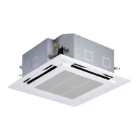
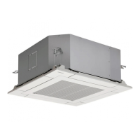
<Comp act 4-way Cas sette Ty pe>
MMU-AP0074MH-E(-TR)
MMU-AP0094MH-E(-TR)
MMU-AP0124MH-E(-TR)
MMU-AP0154MH-E(-TR)
MMU-AP0184MH-E(-TR)
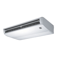
<Ceiling Type>
MMC-AP0154H-E(-TR)
MMC-AP0184H-E(-TR)
MMC-AP0244H-E(-TR)
MMC-AP0274H-E(-TR)
MMC-AP0364H-E(-TR)
MMC-AP0484H-E(-TR)
<Floor Standing Cabinet Type>
MML-AP0074H-E(-TR)
MML-AP0094H-E(-TR)
MML-AP0124H-E(-TR)
MML-AP0154H-E(-TR)
MML-AP0184H-E(-TR)
MML-AP0244H-E(-TR)
<Slim Du ct Type>
MMD-AP0074SPH-E(-TR)
MMD-AP0094SPH-E(-TR)
MMD-AP0124SPH-E(-TR)
MMD-AP0154SPH-E(-TR)
MMD-AP0184SPH-E(-TR)
<Floor Stan ding Type>
MMF-AP0154H-E(-TR)
MMF-AP0184H-E(-TR)
MMF-AP0244H-E(-TR)
MMF-AP0274H-E(-TR)
MMF-AP0364H-E(-TR)
MMF-AP0484H-E(-TR)
MMF-AP0564H-E(-TR)
<Concealed Duct Standard Type>
MMD-AP0074BH-E(-TR),
MMD-AP0124BH-E(-TR),
MMD-AP0154BH-E(-TR),
MMD-AP0184BH-E(-TR),
MMD-AP0274BH-E(-TR),
MMD-AP0364BH-E(-TR),
MMD-AP0564BH-E(-TR)
PRINTED IN JAPAN,
Jul, 2012, ToMo
Indoor unit
Model name:
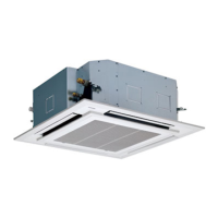
4-way Cassette Type (MMU-AP
∗∗∗
∗∗∗
∗∗∗
∗∗∗
∗∗∗
2H) A08-004
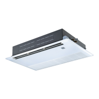
2-way Cassette Type (2 series) (MMU-AP 2WH) A10-007
Fresh Air Intake Indoor Unit Type (MMD-AP 1HFE) A06-016
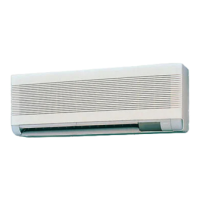
High-wall Type (2 series) (MMK-AP 2H) SVM-05052-1
High-wall Type (3 series) (MMK-AP 3H) SVM-09059
Other indoor units (1 series) A03-009, A03-010, A05-006, A05-007, A06-002
MMD-AP0094BH-E(-TR),
MMD-AP0244BH-E(-TR),
MMD-AP0304BH-E(-TR),
MMD-AP0484BH-E(-TR),
REVISION 1 : Mar.2012
Re-edit version.( file volume down)
Contents have NOT been changed.