17
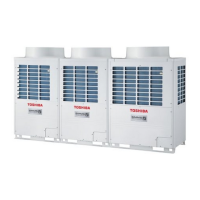
Rear side
Front side
TK sensor (White)
Accumulator
Oil
separator
Liquid tank
Ø6.35 ↔ Ø15.88 between
SV3C valve and discharge pipe
MAP1201H, 1001H, 0801H: Ø8.0 ↔ Ø25.4
MAP0601H, 0501H: Ø8.0 ↔ Ø19.05
between SE3E valve and suction pipe
Ø8.0 ↔ Ø19.05 between
SV41 valve and suction pipe
Ø8.0 ↔ Ø19.05 between
SV42 valve and suction pipe
Ø6.35 ↔ Ø15.88 between
SV2 valve and discharge pipe
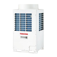
Ø6.35 ↔ Ø15.88 between
SV3C valve and discharge pipe
MAP1201H, 1001H, 0801H: Ø8.0 ↔ Ø25.4
MAP0601H, 0501H: Ø8.0 ↔ Ø19.05
between SE3E valve and suction pipe
Ø8.0 ↔ Ø19.05 between
SV41 valve and suction pipe
Ø8.0 ↔ Ø19.05 between
SV42 valve and suction pipe
Ø6.35 ↔ Ø15.88 between
SV2 valve and discharge pipe
TK1 sensor (Black)
Accumulator side
(Rear side)
TK4 sensor
(Green)
TK2 sensor (Blue)
Front side
TK1 sensor (Black)
Accumulator side
(Rear side)
TK4 sensor
(Green)
TK2 sensor (Blue)
Front side
No.
7
8
Part to be
exchanged
Temperature
sensor positions
and identification
Attachment/
detachment of
pipe fixing rubber
Work procedure
<Rear side of air conditioner>
In this air conditioner, (segmentation system) eyeglass rubber
and SUS fix band are adopted for fixing the vibration system as
one measures to improve the reliability.
<Used positions of SUS fixing band: Total 5 positions>
Remarks
 Loading...