EasyManua.ls Logo

Toshiba MMY-MAP0802FT8-E Service Manual

Toshiba MMY-MAP0802FT8-E
45 pages
To Next Page IconTo Next Page
Page #1 background imageLoading...
Page #1 background image
R410A
FILE NO. A07-004
SERVICE MANUAL
This manual describes about the model which is installed with the passive filter to the fan driving
circuit as the measure against the Europe Harmonic Regulation EN61000-3-12.
The indoor units are same as those of the existing models and they are not especially changed.
For the standard servicing method, refer to the FILE NO. A03-009, A04-008 and A05-004-1.
New models compliance with EMC: IEC61000-3-12
< Outdoor Unit >
Heat Pump Model
MMY-MAP0501HT8-E, MMY-MAP0601HT8-E, MMY-MAP0801HT8-E,
MMY-MAP1001HT8-E, MMY-MAP1201HT8-E
Cooling Only Model
MMY-MAP0501T8-E, MMY-MAP0601T8-E, MMY-MAP0801T8-E,
MMY-MAP1001T8-E, MMY-MAP1201T8-E
Heat Recovery Model
MMY-MAP0802FT8-E, MMY-MAP1002FT8-E, MMY-MAP1202FT8-E
PRINTED IN JAPAN, Dec.,2007 ToMo
Revised Sep. 2009 (1)
Question and Answer IconNeed help?

Do you have a question about the Toshiba MMY-MAP0802FT8-E and is the answer not in the manual?

Toshiba MMY-MAP0802FT8-E Specifications

General IconGeneral
BrandToshiba
ModelMMY-MAP0802FT8-E
CategoryHeat Pump
LanguageEnglish

Summary

Toshiba Super Modular Multi Service Manual

Heat Pump Model Series

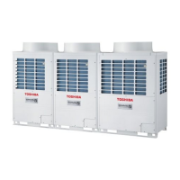
Lists outdoor units for the Heat Pump Model series.

Cooling Only Model Series

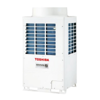
Lists outdoor units for the Cooling Only Model series.

Heat Recovery Model Series

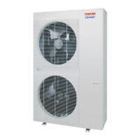
Lists outdoor units for the Heat Recovery Model series.

Key Differences in Main Parts

Newly Changed Contents: Passive Filter Addition

Details the addition of a passive filter and connector for harmonic regulations.

Changes in Refrigerant Amount

Lists reductions in refrigerant amounts for specific models.

Oil Tank Appearance Change

Illustrates the change from a tank-type to a tube-type oil tank.

Outdoor Unit Wiring Diagram

Model Series: MMY-MAP0501HT8-E to MMY-MAP1201HT8-E

Wiring diagram for Heat Pump and Cooling Only models.

Troubleshooting the Passive Filter Circuit

Diagnosis Procedure for Check Codes

Step-by-step guide for diagnosing operational errors related to the passive filter.

Passive Filter Box Components

Diagram of the passive filter box components: Reactor, Resistor, Diode, Capacitor.

P.C. Board Replacement Guide

Table mapping auxiliary codes to the P.C. boards that need replacement.

Outdoor Unit Control Circuit Configuration

Fan Power P.C. Board (MCC-1439) Diagram

Schematic of the fan power supply P.C. board, showing components and connections.

Running Changes

Remote Controller Model Name Update

Details the change of the wired remote controller model name to RBC-AMT31E.

Outdoor Unit Parts Layout: SMMS Series

SMMS Series (A03-009, A04-008) - Rear and Front Views

Exploded view showing component locations on the rear and front sides of the outdoor unit.

Outdoor Unit Parts Layout: SHRM Series

SHRM Series (A05-004-1) - Rear and Front Views

Exploded view showing component locations on the rear and front sides of the outdoor unit.

Refrigerant Piping Diagrams

Inverter Unit (5-12HP) HT8-E Series Piping

Systematic drawing of the refrigerant circuit for inverter units of the HT8-E series.

Refrigerant Piping Diagrams

Inverter Unit (8-12HP) FT8-E Series Piping

Systematic drawing of the refrigerant circuit for specific inverter unit models of the FT8-E series.

Refrigerant Recovery for Compressor Replacement

Work Procedure and Refrigerant Amounts

Steps for refrigerant recovery and a table of refrigerant amounts by system HP and outdoor unit combination.

Parts Replacement Procedures: SMMS Series

SMMS Series: Sensor Locations and Pipe Fixing

Illustrates sensor positions and pipe fixing for vibration reduction in SMMS series.

Parts Replacement Procedures: SMMS Series

SMMS Series: Temperature Sensor and Pipe Fixing Rubber

Details temperature sensor identification and SUS fixing band positions for vibration reduction.

Parts Replacement Procedures: SHRM Series

SHRM Series: Sensor Locations and Pipe Fixing

Illustrates sensor positions and pipe fixing for vibration reduction in SHRM series.

Parts Replacement Procedures: SHRM Series

SHRM Series: Temperature Sensor and Pipe Fixing Rubber

Details temperature sensor identification and SUS fixing band positions for vibration reduction.

Outdoor Unit P.C. Board Exchange Procedures

Checking Fan Power Supply P.C. Board Voltages

Procedure to check output voltages on the fan power supply P.C. board using a tester.

Checking Fan IPDU Connections

Steps to verify lead wire insertion for the fan IPDU and its communication connector.

Passive Filter Circuit Detachment and Assembly

Passive Filter Disassembly Steps

Detailed steps for safely disassembling and removing the passive filter assembly.

Passive Filter Circuit Detachment and Assembly

Removing Rear Panel and Passive Filter Box

Procedures for removing the rear panel and the passive filter box.

Passive Filter Box Internal Check

Instructions for checking internal components of the passive filter box for short circuits or openings.

Passive Filter Circuit Detachment and Assembly

Reassembling the Passive Filter Box

Steps for reassembling the passive filter box by reversing disassembly procedures.

Connector Connection Verification

Checks for proper connection of power supply and passive filter connectors.

Outdoor Unit Exploded Views and Parts List: HT8-E Series

HT8-E Series (5-12HP) Exploded View

Exploded diagram of the outdoor unit for the HT8-E series, showing numbered parts.

Outdoor Unit Exploded Views and Parts List: HT8-E Series

HT8-E Series Parts List

Detailed list of parts with part numbers and quantities for the HT8-E series.

Outdoor Unit Exploded Views and Parts List: HT8-E Series

HT8-E Series Component Locations

Diagram showing numbered component locations on the outdoor unit for the HT8-E series.

Outdoor Unit Exploded Views and Parts List: HT8-E Series

HT8-E Series Parts List (Continued)

Further continuation of the parts list with part numbers and quantities for the HT8-E series.

Refrigeration Circuit Diagram: HT8-E Series

HT8-E Series Refrigerant Flow

Diagram illustrating the refrigerant flow path for the HT8-E series models.

Outdoor Unit Exploded Views and Parts List: HT8-E Series

HT8-E Series Parts List (Continued)

Final part of the parts list with part numbers and quantities for the HT8-E series.

Outdoor Unit Exploded Views and Parts List: HT8-E Series

HT8-E Series Parts List (Continued)

Further continuation of the parts list with part numbers and quantities for the HT8-E series.

Outdoor Unit Exploded Views and Parts List: T8-E Series

T8-E Series (5-12HP) Exploded View

Exploded diagram of the outdoor unit for the T8-E series, showing numbered parts.

Outdoor Unit Exploded Views and Parts List: T8-E Series

T8-E Series Parts List

Detailed list of parts with part numbers and quantities for the T8-E series.

Outdoor Unit Exploded Views and Parts List: T8-E Series

T8-E Series Component Locations

Diagram showing numbered component locations on the outdoor unit for the T8-E series.

Outdoor Unit Exploded Views and Parts List: T8-E Series

T8-E Series Parts List (Continued)

Continuation of the parts list with part numbers and quantities for the T8-E series.

Refrigeration Circuit Diagram: T8-E Series

T8-E Series Refrigerant Flow

Diagram illustrating the refrigerant flow path for the T8-E series models.

Outdoor Unit Exploded Views and Parts List: T8-E Series

T8-E Series Parts List (Continued)

Final part of the parts list with part numbers and quantities for the T8-E series.

Outdoor Unit Exploded Views and Parts List: T8-E Series

T8-E Series Parts List (Continued)

Further continuation of the parts list with part numbers and quantities for the T8-E series.

Outdoor Unit Exploded Views and Parts List: FT8-E Series

FT8-E Series (8-12HP) Exploded View

Exploded diagram of the outdoor unit for the FT8-E series, showing numbered parts.

Outdoor Unit Exploded Views and Parts List: FT8-E Series

FT8-E Series Parts List

Detailed list of parts with part numbers and quantities for the FT8-E series.

Outdoor Unit Exploded Views and Parts List: FT8-E Series

FT8-E Series Component Locations

Diagram showing numbered component locations on the outdoor unit for the FT8-E series.

Outdoor Unit Exploded Views and Parts List: FT8-E Series

FT8-E Series Parts List (Continued)

Continuation of the parts list with part numbers and quantities for the FT8-E series.

Refrigeration Circuit Diagram: FT8-E Series

FT8-E Series Refrigerant Flow

Diagram illustrating the refrigerant flow path for the FT8-E series models.

Outdoor Unit Exploded Views and Parts List: FT8-E Series

FT8-E Series Parts List (Continued)

Final part of the parts list with part numbers and quantities for the FT8-E series.

Outdoor Unit Exploded Views and Parts List: FT8-E Series

FT8-E Series Parts List (Continued)

Further continuation of the parts list with part numbers and quantities for the FT8-E series.

Related product manuals