7
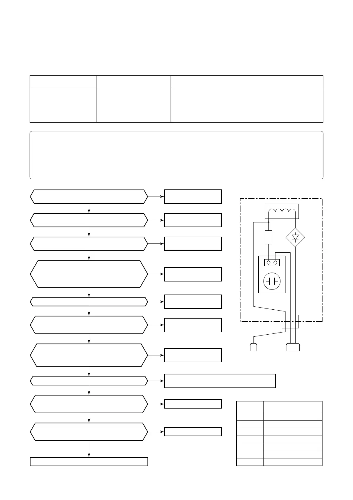
Replace IPDU P.C. board with trouble.
Replace
the electric fuse.
Power supply
P.C. board error.
Check the short circuit of each part, and opening.
And correct the fault parts.
Correct connection
of connector.
Replace
communication line.
I/F P.C. board error
IPDU P.C. board error
Correct connection
of connector.
Correct connection
of connector.
Correct connection
of connector.
Is the passive filter relay connector connected?
Is a passive filter normal?
Is jumper setup of outdoor I/F P.C. board correct?
(Jumpers 7, 8, 9 ON)
Is there no disconnection of communication line
between IPDU and I/F P.C. board?
Is communication connector between IPDU
and I/F P.C. board connected?
Is there voltage fluctuation between
4 and 5 pins of CN600 on I/F P.C. board.
(Measurement by tester: DC0 to 5V, 5 pin GND)
Is the electric fuse of a
Power supply P.C. board for FAN normal?
F500 10A 250V~
Is there voltage fluctuation between
3 and 5 pins of CN600 on I/F P.C. board.
(Measurement by tester: DC0 to 5V, 5 pin GND)
Is the output voltage of a
Power supply P.C. board for FAN normal?
CN502 or CN500 DC 330V
(Judgment : DC180-370V)
Is the connector of the power supply
P.C. board connected certainly?
Power supply P.C. board for FAN MCC-1439
The connector No. CN501, CN502, CN503,
CN505, CN506, CN507?
YES
NO
NO
NO
YES
YES
YES
YES
YES
YES
YES
YES
YES
NO
NO
NO
NO
NO
NO
NO
Both IPDU (No.1, No.2) and fan IPDU
did not return the communication.
P.C. board
to be replaced
Passive filter box
Connector
(YELLOW)
Relay connector
(WHITE)
Electrolytic
capacitor board
Diode
rectifier
Reactor
CN01
RED BLUE YELLOW
YELLOW
RED WHITE
Resistor
Auxiliary
code
IPDU 1
IPDU 2
IPDU 1, 2
Fan IPDU
IPDU 1, fan IPDU
IPDU 2, fan IPDU
IPDU 1, 2, fan IPDU, I/F
01
02
03
04
05
06
07
+
~
3. TROUBLESHOOTING (Passive Filter Circuit)
n Diagnosis procedure for each check code
<SMMS Series (A03-009, A04-008) >
Check code name
[L29] / [CF]
(d07 / AI-NET)
Check code name
IPDU quantity error
Cause of operation
1. Incorrect model setup in service for I/F P.C. board
2. Communication error between IPDU, fan IPDU and I/F
3. IPDU, fan IPDU, I/F P.C. board error
4. Passive filter error
Sub-code:
01: IPDU1 error 02:IPDU2 error
03: IPDU1, 2 error 04:Fan IPDU error
05: IPDU1, fan IPDU error 06:IPDU2, fan IPDU error
07: All IPDU error, Disconnection of communication line between IPDU-I/F P.C. board,
“I/F control P.C. board” error, “Power supply P.C. boad for FAN” error, “Passive filter” error