EasyManua.ls Logo

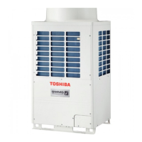
Toshiba MMY-MAP1004HT7P User Manual

Toshiba MMY-MAP1004HT7P
323 pages
To Next Page IconTo Next Page
Page #1 background imageLoading...
Page #1 background image
SERVICE MANUAL
AIR-CONDITIONER (MULTI TYPE)
<SUPER MODULAR MULTI SYSTEM - i>
Outdoor Unit
Model name:
FILE NO. SVM-13024-2
MMY-MAP0804HT8(J)P
MMY-MAP1004HT8(J)P
MMY-MAP1204HT8(J)P
MMY-MAP1404HT8(J)P
MMY-MAP1604HT8(J)P
MMY-MAP0804HT8(J)P-E
MMY-MAP1004HT8(J)P-E
MMY-MAP1204HT8(J)P-E
MMY-MAP1404HT8(J)P-E
MMY-MAP1604HT8(J)P-E
MMY-MAP0804HT8(J)P-TR
MMY-MAP1004HT8(J)P-TR
MMY-MAP1204HT8(J)P-TR
MMY-MAP1404HT8(J)P-TR
MMY-MAP1604HT8(J)P-TR
<Heat Pump Model>
<4-way Cassette Type>
(MMU-AP***4HP-E) (Made in Thailand model) SVM-13-011
<2-way Cassette Type>
(MMU-AP
***
2WH) A10-007
<Concealed Duct Standard Type>
(MMD-AP
***
6BH-E) A12-005
<Slim Duct Type>
(MMD-AP0244SPH-E, AP0274SPH-E) A12-005
Fresh Air Intake Indoor Unit Type
(MMD-AP
****
HFE) A06-016
<Air to Air Heat Exchanger with DX Coil Unit Type>
(MMD-VN
*****
HEXE
*
) A10-022-2
High-wall Type
(MMK-AP
***
3H) (Made in Thailand model) SVM-09-059
Console Type
(MML-AP
****
NH-E) (Made in Thailand model) SVM-11-036
Other indoor units
(MM
*
-AP
*****
H
*
) A10-033
MMY-MAP0804HT7(J)P
MMY-MAP1004HT7(J)P
MMY-MAP1204HT7(J)P
MMY-MAP1404HT7(J)P
MMY-MAP1604HT7(J)P
MMY-MAP0804T8(J)P
MMY-MAP1004T8(J)P
MMY-MAP1204T8(J)P
MMY-MAP1404T8(J)P
MMY-MAP1604T8(J)P
MMY-MAP0804T8(J)P-T
MMY-MAP1004T8(J)P-T
MMY-MAP1204T8(J)P-T
MMY-MAP1404T8(J)P-T
MMY-MAP1604T8(J)P-T
MMY-MAP0804T8(J)P-SG
MMY-MAP1004T8(J)P-SG
MMY-MAP1204T8(J)P-SG
MMY-MAP1404T8(J)P-SG
MMY-MAP1604T8(J)P-SG
<Cooling Only Model>
MMY-MAP0804T8(J)P-ID
MMY-MAP1004T8(J)P-ID
MMY-MAP1204T8(J)P-ID
MMY-MAP1404T8(J)P-ID
MMY-MAP1604T8(J)P-ID
This service manual provides relevant explanations about new outdoor unit (SMMS-i).
Please refer to the following service manuals for each indoor units.

Table of Contents

Questions and Answers:

Toshiba MMY-MAP1004HT7P Specifications

General IconGeneral
BrandToshiba
ModelMMY-MAP1004HT7P
CategoryAir Conditioner
LanguageEnglish

Summary

SAFETY CAUTION

1 Wiring Diagrams

Provides schematic diagrams for electrical connections of outdoor and indoor units for various system configurations.

1-1. Outdoor Unit

Details the wiring diagram for specific outdoor unit models (MMY-MAP0804*, MAP1004*, and MAP1204*).

1-2. Indoor Unit

Covers wiring diagrams for various indoor unit types, including cassette, duct, ceiling, and high-wall models.

5 Control Outline

6 Applied Control and Functions (including Circuit Configuration)

Explains the overall control logic, functions, and applied controls for indoor units and system configurations.

6-1. Indoor Controller Block Diagram

Illustrates the internal block diagram of the indoor unit controller, detailing components and connections.

6-8. Applied Control of Outdoor Unit

Details specific control functions for the outdoor unit, such as fan control, operation modes, and compressor control.

7 TEST OPERATION

7-2. Check Items before Test Operation (before powering-on)

Lists essential checks for electric wiring and system connections required before initiating a test operation.

7-4. Address Setup

Explains the procedures for setting system addresses for indoor and outdoor units, crucial for network communication.

7-5. Troubleshooting in Test Operation

Provides guidance on diagnosing and resolving issues encountered during test operations, including check codes.

8 TROUBLESHOOTING

8-5. Diagnosis procedure for each check code

Details step-by-step procedures for diagnosing faults based on check codes displayed on remote controllers and outdoor units.

11 REPLACING COMPRESSORS

11-1. Compressor Replacement Procedure (Outline)

Outlines the essential steps for safely replacing a compressor, including refrigerant recovery and oil management.

Warning Indications on the Air Conditioner Unit

PRECAUTIONS FOR SAFETY

General Safety Precautions

Covers general safety guidelines including protective gear, handling, and avoiding hazards during installation and maintenance.

Electrical Safety Precautions

Details critical safety measures related to electrical work, circuit breakers, and preventing electric shock.

Grounding and Modification

Emphasizes the importance of proper grounding and prohibits product modifications to prevent hazards.

WARNING

General Safety

Provides essential safety advice for repair work, including handling refrigerants, protective measures, and electrical safety.

Electrical Work Safety

Outlines mandatory safety practices for electrical wiring and repairs, including qualifications and protective gear.

Working at Heights Safety

Specifies safety precautions for tasks performed at heights, including ladder use and securing the work area.

OUTDOOR UNIT PARTS REPLACEMENT METHODS

12-1. Cabinet

Provides instructions for detaching and attaching the outdoor unit cabinet, including screw locations.

12-2. Propeller fan Fan motor

Details the procedure for replacing the propeller fan and fan motor, including CAUTIONary notes for attachment.

12-4. Inverter assembly

Describes the detachment and attachment process for the inverter assembly, including handling of reactor leads and screws.

13 P.C. BOARD EXCHANGE PROCEDURES

13-1. Replacement of Indoor P.C. Boards

Explains the procedure for replacing indoor P.C. boards, including reading and writing EEPROM data.

13-2. Replacement of Outdoor P.C. Boards

Covers the replacement of various outdoor P.C. boards such as interface, fan IPDU, and compressor IPDU.

EXPLODED DIAGRAM/PARTS LIST

Related product manuals