Do you have a question about the Toshiba MW27FN1 and is the answer not in the manual?
Indicates where the unit's rating sheet and safety caution labels are located.
Emphasizes retaining operational manual indications and notices for servicing.
Warns about high voltage parts and avoiding electric shock during servicing.
Stresses using manufacturer-specified parts, especially for safety-critical components.
Advises returning parts and wires to their original configuration after assembly.
Caution regarding handling the explosion-proof CRT to avoid shock hazards.
Advises caution when working on high-voltage circuits to prevent X-ray emission.
Details insulation resistance checks required after performing service procedures.
Specifies required details like model number, version letter, and part number for ordering.
Stresses reading and keeping safety/operating instructions for future reference.
Advises adhering to all unit warnings and following all operating instructions.
Guidelines for unit cleaning and using only manufacturer-approved attachments.
Warns against using the unit near water and placing it on unstable surfaces or carts.
Guidelines for ensuring proper ventilation and selecting correct power sources.
Explains polarized plugs, grounding, and protecting power cords from damage.
Precautions regarding lightning, power lines, and avoiding outlet overloading.
Warnings against object insertion, liquid spills, and explains antenna grounding.
Advises referring servicing to qualified personnel and avoiding self-service.
Lists conditions requiring qualified service for unit repair due to damage or malfunction.
Stresses using manufacturer-specified parts to prevent fire, shock, or other hazards.
Requires post-repair safety checks and following manufacturer mounting guidelines.
Guidelines on product placement, disc tray operation, and connecting to other equipment.
Precautions for sound volume, distortion, and headphone use to prevent hearing or speaker damage.
Warnings against direct laser exposure and using damaged or cracked discs.
Refers to NEC guidelines for proper cable system grounding and connection.
Step-by-step instructions for removing a video tape from the deck chassis without power.
Instructions for safely removing the disc tray by manipulating the rack loading mechanism.
Procedure to cancel the stored 4-digit password in the Rating Level menu.
Steps to unlock the tray lock, which also resets player settings to factory defaults.
Details CRT size, deflection, color system, speaker, and sound output for the TV system.
Lists VCR video system, heads, tape speed, fast forward/rewind times, and picture search.
Covers DVD color system, disc diameter, playback time, search speed, and slow speed.
Details broadcasting system, tuning system, input impedance, and intermediate frequency.
Lists input/output levels, S/N ratios, and frequency responses for video, audio, and hi-fi audio signals.
Details power source, consumption, standby power, and protector components.
Covers safety regulations, operating temperature, and storage conditions.
Specifies the operating humidity range for the unit.
Lists available menu options and functions for TV and VCR modes, including setup and controls.
Details DVD menu options, parental controls, disc playback functions, and system setup.
Lists supported OSD languages for TV/VCR and DVD interfaces.
Covers calendar range, timer events, one-touch recording, sleep timer, and timer back-up.
Lists all functions controllable via the remote unit for TV/VCR and DVD operations.
Enumerates unit features like auto head cleaning, auto tracking, and lists included accessories.
Describes front/rear interface switches, indicators, and connection terminals for various signals.
Provides physical dimensions, weight, and carton specifications for the unit.
Lists material details for the cabinet and PCB, including halogen-free requirements.
Details the removal of back cabinet, CRT PCB, TV/DVD/VCR block, and VCR deck.
Instructions for removing VCR PCB, VCR Deck, DVD PCB/Deck, and Deflection PCB.
Covers removal of top bracket, cassette holder, link units, and levers.
Steps for removing loading motor, tension assembly, and associated bands/springs.
Procedures for removing T brake arm, band, S/T reels, and idler arm assembly.
Instructions for removing cassette opener, A/C head, FE head, and cylinder unit assembly.
Steps for removing capstan DD unit, main cam, pinch roller cam, joint gear, and loading gear units.
Procedures for removing clutch assembly, ring spring, clutch lever, and cassette guide post.
Covers tray removal, main chassis assembly, rack loading, and clamper assembly.
Instructions for removing traverse holder, switch PCB, and rack feed assembly.
Steps for removing relay PCB, gears, and idler arm.
Instructions for removing the feed motor and motor gear.
Detailed steps for safely removing and installing the anode cap, including discharge.
Procedures for removing and installing flat package ICs, including desoldering and soldering.
Lists technical abbreviations from A to L used in the manual for clarity.
Lists technical abbreviations from M to Y used in the manual for clarity.
Instructions on how to enter service modes by pressing specific buttons simultaneously.
Details various service modes and their corresponding operations and standard times.
Table indicating recommended service intervals for various parts based on usage hours.
Procedure to check POWER ON and PLAY/REC total hours displayed on the screen.
Guidelines for cleaning audio control heads, tape running systems, and cylinders.
Steps for replacing the EEPROM IC and ensuring correct data settings are applied.
Lists specialized tools and their part numbers necessary for performing service.
Outlines initial steps for servicing, including volume setting and power cord handling.
Procedure to adjust reel disk height using specific jigs and washers for proper tape movement.
Steps to adjust tension arm position for optimal tape running during playback.
Procedures to confirm playback and back tension torque using specialized tapes and meters.
Procedure to confirm VSR torque using a gauge in Picture Search (Rewind) mode.
Steps to confirm reel brake torque for S Reel and T Reel during Fast Forward mode.
Adjusting the guide roller and confirming reflected picture of stamp mark.
Adjusting the audio/control head height and audio level for optimal performance.
Adjusting X value for maximum envelope waveform output during tape running.
Illustrates the location of key parts for mechanical adjustments on the mechanism assembly.
Outlines necessary precautions, tools, and initial setup for electrical adjustments.
Covers PG Shifter adjustment for the VCR section, including automatic and manual tuning.
Procedure to adjust constant voltage to 135.5 ± 0.5V using a digital voltmeter.
Adjusting bias, drive settings, and screen volume for a proper raster.
Adjusting white balance using gray scale patterns for accurate color reproduction.
Adjusting focus volume to achieve a sharp and distinct picture display.
Adjusting horizontal position and size to minimize screen overscan.
Procedures for adjusting vertical position, size, and linearity for screen alignment.
Adjusting the trapezium to ensure vertical lines of the screen appear parallel.
Adjusting parabola, corner correction, and bright center for optimal picture geometry.
Adjusting the tint control to achieve a straight line for the red color level.
Adjusting color center for RF, AV, and DVD inputs for accurate color display.
Adjusting sub contrast max to achieve normal picture and specified step numbers.
Verifying fixed values for various adjustment items across RF, AV, and DVD modes.
Procedures for static/dynamic convergence and purity using magnets and deflection yoke.
Illustrates the location of parts and wiring connections for electrical adjustments.
High-level block diagram showing DVD solution architecture and signal flow.
Block diagram illustrating signal paths for Y/C, audio, CCD, and head amplifier functions.
Block diagram detailing MICON system functions, connections, and control signals.
Block diagram showing input/output signal paths, including jacks, switches, and LEDs.
Block diagram illustrating the Chroma and IF signal processing circuits.
Block diagram detailing the sound amplifier and surround sound processing circuits.
Block diagram for Hi-Fi audio, head amplifier, and demodulator functions.
Block diagram illustrating the digital comb filter circuitry and its signal connections.
Block diagram showing DVD input/output interfaces and related mixer functions.
Block diagram illustrating the voltage regulator circuits and their power outputs.
Block diagram showing the main functional blocks of the TV system.
Visual layout of the DVD printed circuit board, showing component placement on both sides.
Component layout for the VCR PCB, showing inserted parts on the solder side.
Component layout for the VCR PCB, showing chip-mounted parts on the solder side.
Layouts for Operation, Deflection, and CRT/VM Coil PCBs on the solder side.
Layouts for Relay/SW PCBs, showing inserted and chip-mounted parts.
Detailed schematic of the RF amplifier and DSP section on the DVD PCB.
Schematic diagram illustrating the motor drive circuits for the DVD player.
Detailed schematic of the MPEG processor and its associated circuitry on the DVD PCB.
Schematic diagram for the memory circuits, including SDRAM and Flash memory.
Schematic diagram for the audio and video output circuits, including DAC.
Schematic diagram for the secondary voltage regulator circuits.
Schematic diagram for the Y/C, audio, CCD, and head amplifier circuits on the VCR PCB.
Schematic diagram detailing the MICON (microcontroller) connections and functions.
Schematic diagram for the unit's input and output jacks and switching circuits.
Schematic diagram for the chroma and intermediate frequency (IF) processing circuits.
Schematic diagram for the sound amplifier and surround sound processing circuits.
Schematic diagram for the Hi-Fi audio processing and demodulator functions.
Schematic diagram illustrating the digital comb filter circuitry.
Schematic diagram for the DVD input/output interfaces and related circuitry.
Schematic diagram detailing the various voltage regulator circuits.
Schematic diagram for the TV power supply section, including switching and degauss circuits.
Schematic diagram for the deflection circuits, controlling CRT beam movement.
Schematic diagram illustrating the operation controls and button interfaces.
Schematic diagram for the CRT display and SVM (Service Mode/Vertical) control circuits.
Schematic diagram for the relay and switch circuits, including FG sensor.
Diagram showing how major PCBs and components are interconnected within the system.
Oscilloscope waveforms for the RF amplifier and DSP section.
Oscilloscope waveforms related to the motor drive signals.
Oscilloscope waveforms for the MPEG processor signals.
Oscilloscope waveforms for the audio and video signal processing.
Waveforms for Y/C, audio, CCD, and head amplifier signals.
Oscilloscope waveforms measured from the secondary regulator circuits.
Oscilloscope waveforms related to the MICON microcontroller signals.
Waveforms associated with the deflection control signals.
Oscilloscope waveforms for the sound amplifier and surround sound processing.
Waveforms for the Hi-Fi audio and demodulator circuits.
Oscilloscope waveforms for the chroma and IF signal processing.
Waveforms related to the DVD input/output signals.
Oscilloscope waveforms for the digital comb filter output.
Waveforms related to the CRT display and SVM control signals.
Exploded view showing the assembly of the CRT and associated components.
Exploded view of the main unit, showing VCR, Operation, Deflection, and DVD deck assemblies.
Exploded view of the chassis from the top, detailing component placement and grease points.
Exploded view of the chassis from the bottom, showing component placement and grease points.
Exploded view of the DVD deck, indicating parts and grease application points.
List of mechanical replacement parts with location numbers, TSB P/N, reference, and description.
List of chassis replacement parts including location, TSB P/N, reference, and description.
List of DVD deck replacement parts with location numbers, TSB P/N, reference, and description.
List of replacement resistors and capacitors with location, TSB P/N, reference, and description.
List of replacement diodes with location, TSB P/N, reference, and description.
List of replacement diodes and ICs with location, TSB P/N, reference, and description.
List of replacement transistors with location, TSB P/N, reference, and description.
List of replacement transistors, coils, and transformers with part details.
List of replacement coils, transformers, jacks, and switches with part details.
List of replacement PCB assemblies and miscellaneous items like core beads.
List of miscellaneous replacement parts including cores, batteries, transmitters, and crystals.
List of miscellaneous parts like transmitters and crystals, and codes for capacitor types.
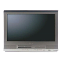
| screen size | 27 inches |
|---|---|
| resolution | 240 lines |
| video out | 1 RCA (rear) |
|---|---|
| video in | 1 RCA (front and rear) |
| audio out | 1 pair L-R (rear) |
| audio inputs | 1 pair L-R (front and rear) |
| coaxial digital output | 1 (DVD only) |
| RF input | 1 (rear) |
| weight | 100 lbs |
|---|---|
| box weight | 110 lbs |
| unit dimensions | 29.1” x 19.3” x 25.4” |
| carton dimensions | 33.5” x 23.5” x 30.5” |