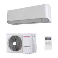
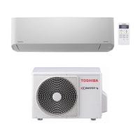
Do you have a question about the Toshiba RAS-05J2KVG-EE and is the answer not in the manual?
Covers reading precautions, observing safety items, and turning off power before maintenance.
Details critical dangers like high voltage, fire, and personal injury risks.
Details electrical characteristics, dimensions, airflow, noise levels, and piping for models.
Illustrates performance variations based on compressor speed and temperature.
Outlines essential precautions and tool requirements for R32 refrigerant handling.
Specifies requirements for copper pipes, joints, and processing for R32 refrigerant.
Lists essential tools and procedures for R32 refrigerant charging.
Detailed exploded views and dimensions of the indoor unit.
Exploded views and dimensions for outdoor units.
Provides comprehensive wiring diagrams for different unit models.
Lists specifications for indoor and outdoor electrical parts.
Illustrates refrigerant path, components, and operating data.
Diagrams detailing MCU functions, remote control, and communication protocols.
Overview of the control system and unit controller roles.
Details cooling, heating, auto, dry, fan control, and basic operations.
Covers ECO, QUIET, Hi-POWER, temporary operations, and remote control features.
Instructions for auto-restart, timer functions, and remote controller indications.
Instructions for selecting location and mounting indoor unit.
Guidelines for outdoor unit placement and precautions.
Procedures for connecting power and internal wiring for units.
Lists optional installation parts and required tools for proper setup.
Initial checks for power, voltage, and basic operational status.
Diagnosing issues using flashing LEDs and remote controller service mode.
Guides for common problems like no power, fan issues, and wiring failures.
Methods to check key components like sensors, valves, and compressors for faults.
Step-by-step guide for replacing indoor unit parts.
Procedures for replacing outdoor unit parts.
Exploded view and list of indoor unit components.
Exploded view and list of outdoor unit components.
| Type | Split System |
|---|---|
| Cooling Capacity | 1.5 kW |
| Power Supply | 220-240V, 50Hz |
| Refrigerant | R32 |
| Weight (Indoor Unit) | 7.0 kg |
