Do you have a question about the Toshiba RAS-07UKPX3 and is the answer not in the manual?
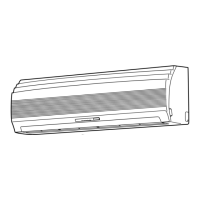
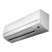
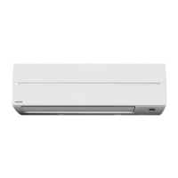
Details on the dimensions and installation of the indoor unit.
Diagrams for outdoor units of multiple series including RAS-13UAH-E3, RAS-10UA-E3.
Diagrams for outdoor units of the RAS-07UAH-E3, RAS-07UA-E3, RAS-07UAX3 models.
Wiring diagram for the RAS-13UKHP-E3 and RAS-13UAH-E3 models.
Wiring diagram for the RAS-10UKHP-E3 and RAS-10UAH-E3 models.
Wiring diagram for the RAS-07UKHP-E3 and RAS-07UAH-E3 models.
Wiring diagrams for multiple RAS models including 13UKP-E3, 13UA-E3, 13UKPX3, 13UAX3, 12UKPX3.
Wiring diagrams for RAS-10UKP-E3, RAS-10UA-E3, RAS-10UKPX3, RAS-10UAX3 models.
Wiring diagrams for RAS-07UKP-E3, RAS-07UA-E3, RAS-07UKPX3, RAS-07UAX3 models.
Specifications for electrical parts of indoor units.
Specifications for outdoor unit parts of RAS-13UAH-E3.
Specifications for outdoor unit parts of RAS-10UAH-E3.
Specifications for outdoor unit parts of RAS-07UAH-E3.
Specifications for electrical parts of various indoor unit models.
Specifications for outdoor unit parts of RAS-13UA-E3.
Specifications for outdoor unit parts of RAS-13UAX3, RAS-12UAX3.
Specifications for outdoor unit parts of RAS-10UA-E3.
Specifications for outdoor unit parts of RAS-07UAX3.
Specifications for outdoor unit parts of RAS-07UA-E3.
Refrigeration cycle diagram for RAS-13UKHP-E3 / RAS-13UAH-E3.
Refrigeration cycle diagram for RAS-10UKHP-E3 / RAS-10UAH-E3.
Refrigeration cycle diagram for RAS-07UKHP-E3 / RAS-07UAH-E3.
Refrigeration cycle diagrams for multiple RAS models.
Refrigeration cycle diagrams for RAS-10UKP-E3, RAS-10UA-E3, RAS-10UKPX3, RAS-10UAX3.
Refrigeration cycle diagrams for RAS-07UKP-E3, RAS-07UA-E3, RAS-07UKPX3, RAS-07UAX3.
Control block diagram for specific HP models.
Control block diagram for various RAS models.
Overview of the air conditioner's control system.
Detailed explanation of the operation circuit.
Describes the fan-only operation mode.
Explains the cooling operation mode.
Details the dry operation mode.
Explains the heating operation mode.
Control to prevent cold drafts from the indoor fan.
Describes the automatic operation mode.
Functionality of the Hi POWER mode.
Control to prevent excessive refrigerating cycle pressure.
Control to prevent indoor heat exchanger freezing.
Procedure for defrost operation during heating.
Control of defrost operation timing.
Control to prevent exceeding specified current values.
Function for automatic restart after power interruption.
Indicator for filter cleaning and its reset.
Function to reduce humidity and prevent mold.
Important safety precautions for installation.
Diagrams showing installation layout for units.
List and description of optional parts for installation.
Inventory of included accessories and installation parts.
Guidelines for selecting the installation place for the indoor unit.
Steps for securely mounting the indoor unit.
Instructions for proper drain hose installation.
Criteria for selecting the outdoor unit installation location.
Procedure and torque specifications for connecting refrigerant pipes.
Steps for evacuating the air conditioner's piping.
Guidelines for connecting the unit's wiring.
Procedure to set the remote control selector switch.
Includes gas leak test, test operation, and auto restart setting.
General steps for troubleshooting the unit.
Initial checks for common operational issues.
Diagnosing issues based on lamp indicators.
Using the remote control for self-diagnosis.
Flowcharts for diagnosing specific operational problems.
Procedure for checking the P.C. board.
Method to adjust the restart delay timer.
Instructions for setting and canceling self-cleaning.
Procedure for replacing indoor unit components.
Procedure for replacing outdoor unit components.
Exploded view and parts list for indoor unit (Heat Pump).
Exploded view and parts list for indoor unit (Cooling).
Detailed exploded view and parts list for the indoor unit.
Exploded view and parts list for outdoor unit RAS-13UAH-E3.
Exploded view and parts list for outdoor unit RAS-10UAH-E3.
Exploded view and parts list for outdoor unit RAS-13UA-E3.
Exploded view and parts list for outdoor unit RAS-10UA-E3.
Exploded view and parts list for outdoor units RAS-07UAX3, RAS-07UA-E3.
Exploded view and parts list for outdoor unit RAS-07UAH-E3.
| Cooling Capacity | 2.0 kW |
|---|---|
| Heating Capacity | 2.5 kW |
| Power Supply | 220-240V, 50Hz |
| Refrigerant | R32 |
| Noise Level (Outdoor) | 48 dB(A) |