Do you have a question about the Toshiba RAS-07UKPX4 and is the answer not in the manual?
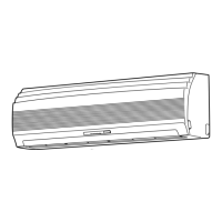
Exploded view and dimensional details of the indoor unit.
Diagrams and dimensions for specific outdoor unit models.
Diagrams and dimensions for specific outdoor unit models.
Wiring diagram specific to RAS-13UKHP-E4 and RAS-13UAH-E4 models.
Wiring diagram specific to RAS-10UKHP-E4 and RAS-10UAH-E4 models.
Wiring diagram specific to RAS-07UKHP-E4 and RAS-07UAH-E4 models.
Wiring diagram specific to RAS-13UKP-E4 and RAS-13UA-E4 models.
Wiring diagrams for RAS-10UKP/UA-E4 and RAS-07UKP/UA-E4 models.
Wiring diagrams for RAS-13UKPX4/UAX4 and RAS-12UKPX4/UAX4 models.
Wiring diagrams for RAS-10UKPX4/UAX4 and RAS-07UKPX4/UAX4 models.
Electrical part specifications for indoor units of specific HP models.
Electrical part specifications for the RAS-13UAH-E4 outdoor unit.
Electrical part specifications for the RAS-10UAH-E4 outdoor unit.
Electrical part specifications for the RAS-07UAH-E4 outdoor unit.
Electrical part specifications for various indoor unit models.
Electrical part specifications for the RAS-13UA-E4 outdoor unit.
Electrical part specifications for RAS-13UAX4/12UAX4 outdoor units.
Electrical part specifications for RAS-10UA-E4/10UAX4 outdoor units.
Electrical part specifications for the RAS-07UAX4 outdoor unit.
Electrical part specifications for the RAS-07UA-E4 outdoor unit.
Refrigeration cycle diagram for RAS-13UKHP-E4/13UAH-E4 models.
Refrigeration cycle diagram for RAS-10UKHP-E4/10UAH-E4 models.
Refrigeration cycle diagram for RAS-07UKHP-E4/07UAH-E4 models.
Refrigeration cycle diagrams for multiple RAS-13/12UKP/UAX4 models.
Refrigeration cycle diagrams for RAS-10UKP/UA-E4 and RAS-10UKPX4/UAX4 models.
Refrigeration cycle diagrams for RAS-07UKP/UA-E4 and RAS-07UKPX4/UAX4 models.
Control block diagram for specific HP models.
Control block diagram for various UKP/UAX4 models.
Overview of the air conditioner's control system and its components.
Detailed description of the air conditioner's operational circuits.
Explains the functionality and operation of the Hi POWER mode.
Describes the control mechanism for high-temperature limits.
Describes the control mechanism for low-temperature limits.
Details the defrost operation procedure and conditions.
Explains the current limit control for preventing overload.
Information on the auto restart function after power interruption.
Explains the filter check indicator and its reset procedure.
Describes the self-cleaning function for moisture reduction.
Details the operation and benefits of the QUIET mode.
Explains the COMFORT SLEEP mode for quiet and energy-saving operation.
Crucial safety precautions to be followed during installation.
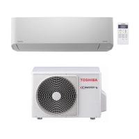
Visual guide illustrating the installation layout of units.
General installation procedures and considerations.
Specific installation instructions for the indoor unit.
Specific installation instructions for the outdoor unit.
Steps to follow for systematic troubleshooting.
Initial checks for power supply and connections before diagnosing faults.
Basic assessment of unit behavior and potential fault causes.
Using the remote control to access and interpret self-diagnosis codes.
Flowcharts to guide the diagnosis process for specific problems.
Troubleshooting steps for the remote control and related P.C. board issues.
Procedures for replacing parts within the indoor unit.
Procedures for replacing parts within the outdoor unit.
Exploded view and parts list for heat pump indoor units.
Exploded view and parts list for cooling indoor units.
Exploded view and parts list for specific indoor unit models.
Exploded view and parts list for specific indoor unit models.
Exploded view and parts list for the RAS-13UAH-E4 outdoor unit.
Exploded view and parts list for the RAS-10UAH-E4 outdoor unit.
Exploded view and parts list for the RAS-13UA-E4 outdoor unit.
Exploded view and parts list for the RAS-10UA-E4 outdoor unit.
Exploded view and parts list for RAS-13UAX4/12UAX4 outdoor units.
Exploded view and parts list for the RAS-10UAX4 outdoor unit.
Exploded view and parts list for RAS-07UAX4/07UA-E4 outdoor units.
Exploded view and parts list for the RAS-07UAH-E4 outdoor unit.
| Brand | Toshiba |
|---|---|
| Model | RAS-07UKPX4 |
| Category | Air Conditioner |
| Language | English |