Do you have a question about the Toshiba RAS-07EKV-EE and is the answer not in the manual?
Crucial safety guidelines for R410A, power disconnection, and general dangers.
Details on electric characteristics, noise, dimensions, piping, wiring, and temperature range.
Safety, materials, and procedures for R410A refrigerant and piping installation.
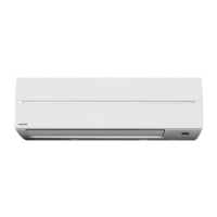
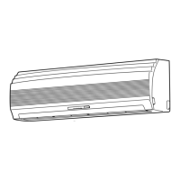
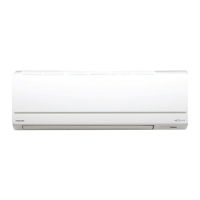
Detailed diagrams of the indoor unit components and dimensions.
Detailed diagrams of the outdoor unit components and dimensions.
Diagram showing electrical connections and components for the indoor unit.
Specifications for indoor unit electrical parts like fan motor and sensors.
Specifications for outdoor unit electrical parts like reactor and sensors.
Diagrams illustrating refrigerant flow for different model series.
Block diagram showing the indoor unit's MCU and control functions.
Block diagram for the outdoor unit's inverter assembly and MCU.
Explanation of unit control, operation modes, and controller roles.
Procedures for installing units, piping, wiring, tools, and final checks.
Methods for diagnosing issues using LED indicators, remote controller, and symptom checks.
Step-by-step guides for replacing key parts like panels, motors, and boards.
Exploded diagrams and part numbers for indoor unit components.
Exploded diagrams and part numbers for outdoor unit components.
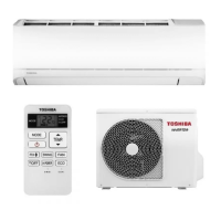
| Type | Split System |
|---|---|
| Cooling Capacity | 2.0 kW |
| Heating Capacity | 2.5 kW |
| Energy Efficiency Ratio (EER) | 3.21 |
| Coefficient of Performance (COP) | 3.61 |
| Power Supply | 220-240V, 50Hz |
| Refrigerant | R410A |
| Outdoor Unit Dimensions (W x H x D) | 660 x 530 x 240 mm |
| Weight (Indoor Unit) | 9 kg |
| Noise Level (Outdoor Unit) | 48 dB(A) |