Do you have a question about the Toshiba RAS-07BKVG-E and is the answer not in the manual?
Details on R32 refrigerant properties and safety precautions.
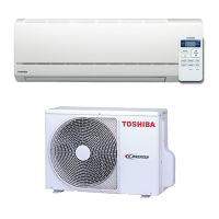
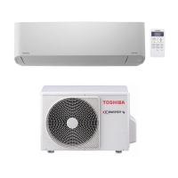
Detailed technical specifications for different air conditioner models.
Graphs showing operational characteristics like current vs. compressor speed.
Graphs illustrating capacity changes based on outside temperature.
Safety precautions for handling R32 refrigerant during installation and servicing.
Guidelines for installing refrigerant piping, including materials, joints, and processing.
Lists tools required for refrigerant work, distinguishing between exclusive and general tools.
Step-by-step procedure for recharging refrigerant into the air conditioner system.
Procedures and materials for brazing refrigerant pipes, including filler materials and flux.
Diagrams showing the construction and dimensions of the indoor unit.
Diagrams illustrating the construction and dimensions of the outdoor unit for specific models.
Diagrams showing the construction and dimensions of the outdoor unit for the RAS-16BAVG-E model.
List of electrical parts for the indoor unit with their specifications.
List of electrical parts for the outdoor unit with their specifications.
Schematic diagrams illustrating the refrigerant cycle for different air conditioner models.
Table showing operational data (temperature, pressure, speed) for cooling and heating modes.
Block diagram illustrating the control functions and components of the indoor unit.
Block diagram of the outdoor unit's inverter assembly, showing control logic.
Overview of how the air conditioner's system controls operation, including indoor and outdoor units.
Details various operating modes and component controls like fan, capacity, and louver.
Details on the auto restart function and its setup/cancellation.
Explains remote controller parts, operations, special functions, and indicators.
Illustrates the overall installation layout for indoor and outdoor units.
Covers installation steps and optional/accessory parts required for the unit.
Instructions for installing the indoor unit, including location, mounting, piping, and drainage.
Guidelines for installing the outdoor unit, including location, cold regions, and piping connection.
Instructions for electrical connections, including wiring, power supply, and diagrams.
Various procedures including gas leak test, remote control selection, test operation, and auto restart.
Power, voltage, normal operation checks, and initial diagnostic steps.
Interpreting indoor LED codes and using remote for self-diagnosis.
Detailed table of check codes, causes, and recommended actions for troubleshooting.
Safety warnings for working with inverters, control boards, and high-voltage components.
Troubleshooting power, remote control, and fan motor issues for the indoor unit.
Steps to diagnose and resolve issues with the remote controller.
Diagnosing and resolving issues related to wiring failures between units.
Simple methods for checking main components like sensors, valves, and coils.
Diagnosing issues specifically within the outdoor unit's inverter assembly.
Procedures for inspecting and checking the indoor unit's PC board for defects.
Diagram showing PC board layout and sensor resistance characteristics.
Checking procedures for various indoor and outdoor unit components like sensors, motors, and valves.
Procedures to determine if the outdoor fan motor is functioning correctly.
Steps to set and cancel the self-cleaning function of the air conditioner.
Procedures for replacing main parts of the indoor unit, including panel, filters, motor, and sensors.
Procedure for replacing the microcomputer assembly on the indoor unit.
Procedures for disassembling and assembling the outdoor unit for specific models.
Procedures for disassembling and assembling the outdoor unit for the RAS-16BAVG-E model.
Exploded view and part list for the indoor unit components.
Exploded view and part list for specific indoor unit components (Part-E).
Exploded view and part list for outdoor unit models RAS-05, 07, 10BAVG-E.
Exploded view and part list for outdoor unit model RAS-13BAVG-E.
Exploded view and part list for outdoor unit model RAS-16BAVG-E.
Exploded view and part list for specific outdoor unit components (Part-E).
| Cooling Capacity | 2.0 kW |
|---|---|
| Refrigerant | R32 |
| Heating Capacity | 2.5 kW |
| Power Supply | 220-240V, 50Hz |
| Type | Split System |