Do you have a question about the Toshiba RAS-07NKHD-E and is the answer not in the manual?
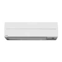
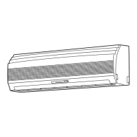
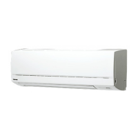
Diagrams detailing the dimensions and features of the indoor unit.
Diagrams for outdoor units RAS-13/10UAH-E3 and RAS-13/10UA-E3, showing dimensions and mounting.
Diagrams for outdoor units RAS-07UAH-E3 and RAS-07UA-E3, showing dimensions and mounting.
Detailed wiring schematic for the RAS-13NKHD-E and RAS-13UAH-E3 models.
Wiring schematics for RAS-10NKHD/UAH-E3 and RAS-07NKHD/UAH-E3 models.
Detailed wiring schematic for the RAS-13NKD-E and RAS-13UA-E3 models.
Wiring schematics for RAS-10NKD/UA-E3 and RAS-07NKD/UA-E3 models.
List and specifications of electrical components for indoor units RAS-13/10/07NKHD-E.
List and specifications of electrical components for outdoor unit RAS-13UAH-E3.
List and specifications of electrical components for outdoor unit RAS-10UAH-E3.
List and specifications of electrical components for outdoor unit RAS-07UAH-E3.
List and specifications of electrical components for indoor units RAS-13/10/07NKD-E.
List and specifications of electrical components for outdoor unit RAS-13UA-E3.
List and specifications of electrical components for outdoor unit RAS-10UA-E3.
List and specifications of electrical components for outdoor unit RAS-07UA-E3.
Diagram showing refrigerant flow and operating parameters for RAS-13NKHD-E/RAS-13UAH-E3.
Diagram showing refrigerant flow and operating parameters for RAS-10NKHD-E/RAS-10UAH-E3.
Diagram showing refrigerant flow and operating parameters for RAS-07NKHD-E/RAS-07UAH-E3.
Diagram showing refrigerant flow and operating parameters for RAS-13NKD-E/RAS-13UA-E3.
Diagram showing refrigerant flow and operating parameters for RAS-10NKD-E/RAS-10UA-E3.
Diagram showing refrigerant flow and operating parameters for RAS-07NKD-E/RAS-07UA-E3.
Control logic diagram for heat pump operation, detailing MCU and remote control functions.
Control logic diagram for cooling operation, detailing MCU and remote control functions.
Overview of the air conditioner's control system, components, and functions.
Details on vertical air flow louver operation, including swing and fixed positions.
Explanation of indoor fan motor operation and speed control for different modes.
Sequence of operations when turning on the unit and executing commands.
Fan Only mode operation, including AUTO and manual speed settings.
Control logic for compressor, outdoor fan, and display during cooling.
Control logic for compressor, 4-way valve, and fans during dry operation.
Control logic for compressor, 4-way valve, and fans during heating.
How the unit selects between Cooling, Fan only, or Heating modes automatically.
Operating the Plasma Air-Purifier with other modes or independently.
Flowchart detailing Plasma Air-Purifier operation logic and error handling.
Interaction between indoor fan speed and Plasma Air-Purifier operation.
How Hi POWER mode affects cooling/heating operations and fan speed.
Control to prevent excessive rise in refrigerating cycle pressure.
Control to prevent the indoor heat exchanger from freezing.
Procedure for defrosting the outdoor unit during heating operation.
Conditions that trigger the start of the defrost operation.
Details on the duration and cycles of the defrost operation.
Control to prevent compressor current from exceeding specified values.
Functionality for automatic unit restart after power interruption.
Guide on how to enable the auto restart function on the indoor unit.
Guide on how to disable the auto restart function.
Explanation of the filter check lamp and how to reset it.
Instructions for turning off the filter check lamp.
Details on the self-cleaning function for reducing coil humidity.
Procedure to cancel the self-cleaning function.
Procedure to set the self-cleaning function.
Important safety precautions and warnings for qualified personnel during installation.
Diagrams showing placement and connection points for indoor and outdoor units.
List of optional parts required for installation, including piping and insulation.
List of standard accessories and installation parts included with the unit.
Guidelines for selecting an appropriate location for the indoor unit.
Instructions for drilling holes and mounting the indoor unit's installation plate.
Power source requirements and connection methods for indoor unit wiring.
Step-by-step guide on how to connect the power cord to the indoor unit.
Instructions for forming and installing refrigerant piping and drain hoses for the indoor unit.
Steps for securely mounting the indoor unit onto the installation plate.
Instructions for routing and ensuring proper drainage from the indoor unit.
Guidelines for selecting an appropriate location for the outdoor unit.
Steps for connecting refrigerant pipes, including cutting, flaring, and tightening.
Procedure for evacuating air and moisture from refrigerant pipes using a vacuum pump.
Instructions for connecting the connecting cable between indoor and outdoor units.
Guide to setting the remote control selector switch for multi-unit installations.
Method for checking refrigerant connections for gas leaks.
General steps for troubleshooting, starting with basic checks and progressing to self-diagnosis.
Essential preliminary checks for power supply, cable connections, and unit operation.
Interpreting operational status and diagnosing faults based on lamp indicators.
Diagnosing failures based on blinking patterns of the operation and timer lamps.
Using the remote control to access and interpret error codes for self-diagnosis.
Step-by-step instructions for entering service mode and retrieving diagnostic codes.
Flowcharts to diagnose and resolve specific operational issues.
Diagnosing issues with the remote control or the indoor unit's P.C. board.
Procedures and precautions for inspecting the indoor unit's P.C. board for defects.
Instructions to shorten the restart delay timer duration using the remote control.
Guide to setting or cancelling the self-cleaning function.
Troubleshooting specific issues with the air purifier and minus ion generator.
Procedure to check if the air purifier and its components are functioning correctly.
Procedure to check if the minus ion generator is functioning correctly.
Procedures for removing and replacing parts of the indoor unit, starting with the front panel.
Procedure for replacing the indoor unit's electrical part box and LED unit.
Procedure for replacing the indoor unit's horizontal louver assembly.
Procedure for replacing the indoor unit's heat exchanger.
Procedure for replacing the indoor unit's cross flow fan and motor.
Procedure for replacing the indoor unit's base bearing assembly.
Common procedure for disassembling the outdoor unit's cabinets and covers.
Procedure for replacing the outdoor unit's compressor capacitor.
Procedure for replacing the outdoor unit's fan motor capacitor.
Exploded view and parts list for the indoor unit's E-Parts Assembly.
Exploded view and parts list for the indoor unit, covering various assemblies.
Exploded view and parts list for the outdoor unit RAS-13UAH-E3.
Exploded view and parts list for the outdoor unit RAS-10UAH-E3.
Exploded view and parts list for the outdoor unit RAS-13UA-E3.
Exploded view and parts list for the outdoor unit RAS-10UA-E3.
Exploded view and parts list for the outdoor unit RAS-07UA-E3.
| Brand | Toshiba |
|---|---|
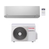
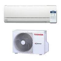
| Model | RAS-07NKHD-E |
| Category | Air Conditioner |
| Language | English |