EasyManua.ls Logo

Toshiba RAS-10N3AV2-A User Manual

Toshiba RAS-10N3AV2-A
116 pages
To Next Page IconTo Next Page
Page #1 background imageLoading...
Page #1 background image
R410A
SERVICE MANUAL
SPLIT TYPE
January, 2013
FILE NO. SVM-13001
SPLIT TYPE
Indoor Unit Outdoor Unit
<High Wall, Heat Pump Type> <Heat Pump Type>
RAS-13N3KV2-A / RAS-13N3AV2-A
RAS-10N3KV2-A / RAS-10N3AV2-A
RAS-16N3KV2-A / RAS-16N3AV2-A

Table of Contents

Question and Answer IconNeed help?

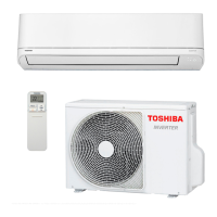
Do you have a question about the Toshiba RAS-10N3AV2-A and is the answer not in the manual?

Toshiba RAS-10N3AV2-A Specifications

General IconGeneral
Power Supply220-240V, 50Hz
RefrigerantR410A
Energy Efficiency Ratio (EER)3.21
Coefficient of Performance (COP)3.61
Outdoor Unit Dimensions (W x H x D)660 x 530 x 240 mm
TypeSplit System

Summary

1. SAFETY PRECAUTIONS

General Safety Instructions

Crucial safety instructions for installation, operation, and handling refrigerant.

2. SPECIFICATIONS

3. REFRIGERANT R410A

Safety During Installation/Servicing

Safety precautions for R410A installation and servicing.

Refrigerant Piping Installation

Guidelines for refrigerant piping installation, materials, and joints.

Piping Materials and Joints

Details on copper pipes, joints, and their specifications.

Piping Material Processing

Procedures and precautions for processing refrigerant piping materials.

Flare Connecting Procedures

Steps and precautions for connecting flare pipes.

3-3. Tools for R410A

Required Tools

Lists tools exclusive for R410A and general tools.

3-4. Recharging of Refrigerant

3-5. Brazing of Pipes

Brazing Materials and Flux

Details on brazing filler materials and the necessity of flux.

Brazing Method to Prevent Oxidation

Method for brazing to prevent oxidation using nitrogen gas flow.

4. CONSTRUCTION VIEWS

Indoor Unit Construction Details

Exploded views and dimensions for the indoor unit.

Outdoor Unit Construction Details

Exploded views and dimensions for the outdoor unit.

5. WIRING DIAGRAM

Wiring Diagram for 10/13k Models

Specific wiring diagram for 10k and 13k indoor units.

Wiring Diagram for 16k Model

Specific wiring diagram for the 16k indoor unit.

6. SPECIFICATIONS OF ELECTRICAL PARTS

Indoor Unit Electrical Parts Specs

Specifications for electrical components of the indoor unit.

Outdoor Unit Electrical Parts Specs

Specifications for electrical components of the outdoor unit.

7. REFRIGERANT CYCLE DIAGRAM

Cycle Diagram for 10/12k Models

Refrigerant cycle diagram for specific models.

Cycle Diagram for 13/12k Models

Refrigerant cycle diagram for specific models.

Cycle Diagram for 16k Model

Refrigerant cycle diagram for specific models.

7-2. Operation Data

8. CONTROL BLOCK DIAGRAM

Indoor Unit Control Diagram

Control block diagram for the indoor unit and remote controller.

Outdoor Unit Control Diagram

Control block diagram for the outdoor unit.

9. OPERATION DESCRIPTION

Air Conditioner Control Outline

Overview of the air conditioner's control system.

Controller Roles and Signals

Roles of indoor/outdoor controllers and inter-unit signals.

9-2. Operation Description

Basic Operation Modes

Covers basic, cooling/heating, AUTO, and DRY operations.

Motor and System Controls

Covers fan motor, capacity, current, and protective controls.

Defrost and Louver Control

Details defrost and louver control functions.

Special Operation Modes

Covers ECO, Temporary, and Quiet modes.

Operation Control Flow

Operation Mode Flows

Cooling/Heating Operation Flow

Detailed flowcharts for specific operation modes.

AUTO Operation Flow

Detailed flowcharts for specific operation modes.

DRY Operation Flow

Detailed flowcharts for specific operation modes.

Indoor Fan Speed Control (Cooling)

Indoor Fan Speed Control (Heating)

Cold Draft Prevention Control

Control to prevent cold drafts during heating operation.

3. Outdoor fan motor control

4. Capacity Control

5. Current Release Control

6. Heat Exchanger Protective Control

7. Defrost Control (Heating Operation)

8. Louver Control

9. ECO Operation

10. Temporary Operation

11. Discharge Temperature Control

12. Pulse Modulating Valve (P.M.V.) Control

13. Self-Cleaning Function

14. Remote-A or B Selection

15. QUIET Mode

16. COMFORT SLEEP Mode

17. Short Timer

18. One-Touch Comfort

19. Hi-POWER Mode

20. FILTER Indicator

9-3. Auto Restart Function

Canceling Auto Restart Function

Steps to cancel the automatic restart feature.

Power Failure During Timer Operation

Behavior during power failure with timer active.

9-4. Remote Controller Functions

Remote Controller Parts and Operation

Identifies remote components and explains basic operations.

Remote Control Operations

Detailed remote control operations for various modes.

Preset Operation

Auto Restart Operation

Automatically restarts the conditioner after a power failure.

Quiet Operation

Operation for quietness at low fan speed.

Comfort Sleep Operation

Saves energy and controls airflow during sleep.

Remote Controller Display Indications

10. INSTALLATION PROCEDURE

Installation Diagrams

Visual guides for indoor and outdoor unit installation layout.

Optional Installation Parts

Lists optional parts for installation.

Outdoor Unit Fixing Bolt Arrangement

Outdoor unit mounting bolt configuration.

Accessory and Installation Parts List

Inventory of included accessories and installation components.

Installation and Servicing Tools

Lists essential tools for installation and servicing.

10-3. Indoor Unit Installation

Installation Place Selection

Guidelines for choosing the optimal indoor unit location.

Remote Control Placement

Recommendations for remote control positioning.

Cutting Hole and Mounting Plate

Procedures for hole cutting and installation plate mounting.

Wiring Connection (Indoor Unit)

Wire Operation for Remote Controller

Piping and Drain Hose Installation

Indoor Unit Fixing Procedures

Drainage Setup Instructions

10-4. Outdoor Unit Installation

Installation Place Selection

Guidelines for choosing the optimal outdoor unit location.

Refrigerant Adding Precautions

Safety guidelines for adding refrigerant.

Refrigerant Piping Connection

Flaring Process

Procedure for flaring copper pipes for connections.

Tightening Connection Process

Steps for properly tightening pipe connections.

Evacuating Procedures

Air Purge

Removing air from the system using a vacuum pump.

Vacuum Pump Usage

Guidelines for using a vacuum pump correctly.

Electrical Work

Wiring Connection (Outdoor Unit)

Gas Leak Test

Remote Control A-B Selection

Test Operation

Auto Restart Setting

11. TROUBLESHOOTING GUIDE

Inverter Handling Precautions

Safety measures for handling the inverter unit.

Outdoor Unit Control Section Precautions

Safety measures for inspecting the outdoor unit's control section.

11-1. First Confirmation

Power Supply Confirmation

Confirming the power supply breaker is operating normally.

Power Voltage Confirmation

Confirming the power voltage is within the specified range.

Normal Operation Identification

Identifying normal program operations that may seem like issues.

11-3. Judgment by Flashing LED of Indoor Unit

11-4. Self-Diagnosis by Remote Controller

Using Remote Controller in Service Mode

Guide to using the remote for self-diagnosis.

11-5. Symptom-Based Troubleshooting

Indoor Unit & Remote Control Issues

Troubleshooting for indoor unit and remote control problems.

Power Issues After P.C. Board Replacement

Steps for diagnosing power problems after P.C. board replacement.

Indoor Fan Motor Not Operating

Diagnostic steps for a non-operational indoor fan motor.

Indoor Fan Motor Auto-Start Behavior

Troubleshooting for an indoor fan motor that starts automatically.

Remote Controller Troubleshooting

Detailed steps for diagnosing remote control failures.

11-5-2. Wiring Failure

Outdoor Unit Does Not Operate

Troubleshooting steps when the outdoor unit does not operate due to wiring.

Outdoor Unit Stops After Starting

Troubleshooting for outdoor unit stopping after operation starts.

11-6. Main Parts Checking

11-7. Diagnose Trouble in Outdoor Unit

Inverter Assembly Diagnosis

Diagnostic flowchart for the outdoor unit's inverter assembly.

11-8. Checking Main Parts

Checking Indoor P.C. Board

Procedures for checking the indoor unit's P.C. board.

11-8-2. P.C. Board Layout

11-8-3. Indoor Unit Parts Checking

11-8-4. Outdoor Unit Parts Checking

11-9. Judge Outdoor Fan Motor Status

12. HOW TO REPLACE MAIN PARTS

General Replacement Warnings

Crucial safety warnings before replacing parts.

Indoor Unit Part Replacement Procedures

Step-by-step guide for replacing indoor unit parts.

Front Panel Replacement

Procedures for removing and installing the indoor unit's front panel.

Electric Parts Box Assembly Replacement

Procedures for replacing the electric parts box.

Horizontal Louver Replacement

Procedures for replacing the horizontal louver.

Evaporator (Heat Exchanger) Replacement

Procedures for replacing the main heat exchanger.

Bearing Replacement

Procedures for replacing the bearing.

Fan Motor Replacement

Procedures for removing and installing the fan motor.

Cross Flow Fan Reassembly

Instructions for correctly reassembling the cross flow fan.

12-2. Microcomputer Replacement

12-3. Outdoor Unit Part Handling

Outdoor Unit Part Detachment

Procedures for detaching major outdoor unit components.

Outdoor Unit Part Attachment

Procedures for attaching major outdoor unit components.

Front Cabinet Replacement

Procedures for removing and installing the outdoor unit's front cabinet.

Inverter Assembly Replacement

Procedures for replacing the inverter assembly with safety precautions.

Control Board Assembly Replacement

Procedures for removing and mounting the control board assembly.

Side Cabinet Replacement

Procedures for replacing the side cabinets.

Fan Motor Replacement

Procedures for replacing the outdoor fan motor.

Compressor Replacement

Procedures for replacing the compressor.

Reactor Replacement

Procedures for replacing the reactors.

Expansion Valve Coil Replacement

Procedures for replacing the expansion valve coil.

Fan Guard Replacement

Procedures for replacing the fan guard.

Temperature Sensor Installation

Installation procedures for various temperature sensors.

Temperature Sensor Replacement for Servicing

Procedures for replacing temperature sensors for servicing.

13. EXPLODED VIEWS AND PARTS LIST

Indoor Unit Parts List

Exploded view and list of indoor unit components.

Indoor Unit Assemblies

Exploded view and list of indoor unit assemblies.

Outdoor Unit Parts List

Exploded view and list of outdoor unit components.

P.C. Board Layout

Layout of P.C. boards and sensor characteristic tables.

Related product manuals